Driveshaft assembly with indexing means

a technology of indexing means and driveshafts, which is applied in the direction of fuel injecting pumps, machines/engines, instruments, etc., can solve the problems of difficult to accommodate the specific lift range requirements of different eui, ui, and the travel requirements of different plungers, and achieves the effect of simple and cheaper solutions

Active Publication Date: 2020-02-11
DELPHI TECH IP LTD
View PDF15 Cites 0 Cited by
  • Summary
  • Abstract
  • Description
  • Claims
  • Application Information

AI Technical Summary

Benefits of technology

[0012]It is an object of the present invention to provide an improved driveshaft assembly which at least mitigates the above mentioned problems.
[0014]The present invention enables different values of maximum lift to be achieved using a single cam and shaft combination, i.e. a variable plunger lift is enabled for a single cam and shaft combination. Accordingly, a required value of maximum lift can be selected by use of the same cam and shaft, avoiding the need to use a multiple cam and / or rocker arm combinations to achieve different values of maximum lift.
[0021]The present invention provides a simpler and cheaper solution than prior art driveshaft assemblies.

Problems solved by technology

A known disadvantage of the prior art embodiment such as that illustrated in FIGS. 1a and 1b is that the maximum lift Lmax of the driveshaft assembly 1, and therefore the travel of the plunger 90, is predetermined and fixed, as each driveshaft assembly has a set value of B and set maximum value of A. To obtain a different value for the travel of the plunger 90, it is necessary to disassemble the driveshaft assembly 1 by removing the cam 2 from the shaft 12, and replacing it with an alternative cam having a different external profile, i.e. a different value of B and / or maximum A, and / or by replacing the rocker arm or changing the pivot point of the rocker arm.
Accordingly, in prior art embodiments, it is difficult to accommodate the differing plunger travel requirements.
For example, it is difficult to accommodate the specific lift range requirements of different EUI, UI and EUP families, which could typically range from 9 mm to 19 mm.

Method used


Image

  • Driveshaft assembly with indexing means
  • Driveshaft assembly with indexing means
  • Driveshaft assembly with indexing means

Examples


Embodiment Construction

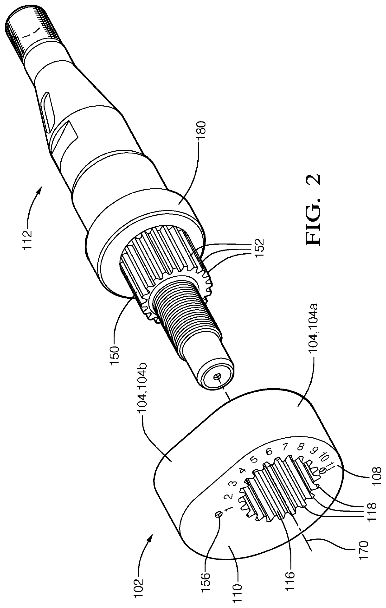
[0033]Referring initially to FIG. 2, the present invention comprises a driveshaft assembly 100 comprising a cam 102 and a shaft 112. The cam 102 comprises a base cylinder section 108, having a longitudinal central axis 170, and an integral further section 110, protruding from part of the circumference of the base cylinder section 108. An outer surface 104 of the cam 102 is defined by an outer surface 104a of the base cylinder section 108, and an outer surface 104b of the further section 110.

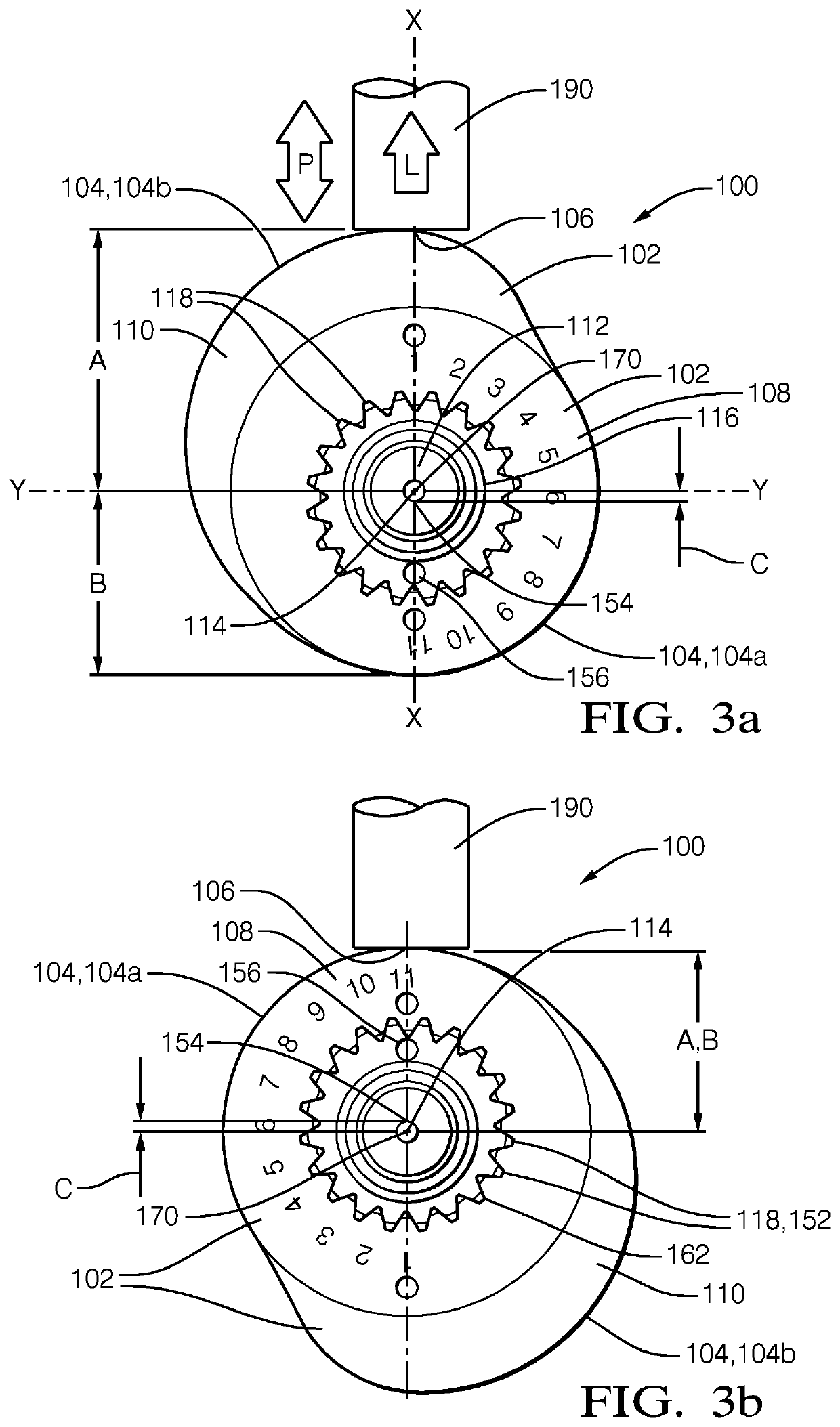
[0034]In the illustrated embodiment, the driveshaft assembly 100 is arranged to act upon a reciprocating component comprising a plunger 190 (shown in FIGS. 3a, 3b, 5a, 5b, 7a and 7b).

[0035]A longitudinally extending bore 116 is provided through the base cylinder section 108.

[0036]The bore 116 is provided with a first set of splines, comprising a plurality of internal splines 118 defined by a plurality of troughs and peaks.

[0037]An annular section 150 of the shaft 112 is provided a second set of s...


PUM


Abstract

A driveshaft assembly, for example in an Electronic Unit Injector, Unit Injector or Electronic Unit Pump testing machine, wherein an indexing arrangement, such as complementary external and internal splines, enables a cam to be mounted on a shaft at a number of discreet positions, each providing a different offset of a central axis of the base cylinder section from a central axis of the shaft, each position providing a different maximum lift value of a plunger in contact with the cam, directly or via a rocker arm.

Description

CROSS REFERENCE TO RELATED APPLICATIONS[0001]This application is a national stage application under 35 USC 371 of PCT Application No. PCT / EP2015 / 068583 having an international filing date of Aug. 12, 2015, which is designated in the United States and which claimed the benefit of GB Patent Application No. 1415964.4 filed on Sep. 10, 2014 the entire disclosures of each are hereby incorporated by reference in their entirety.TECHNICAL FIELD[0002]The present invention relates to a driveshaft assembly, and more specifically to a cam and shaft for a driveshaft assembly.BACKGROUND OF THE INVENTION[0003]Fuel pumping and pressurising plungers of Electronic Unit Injectors (EUI), Unit Injectors (UI) and Electronic Unit Pumps (EUP), are operated in a reciprocating manner. In a known driveshaft arrangement or assembly 1, as illustrated in FIGS. 1a and 1b, reciprocating motion of a plunger 90, as indicated by arrow P, is caused by a rotating cam 2 located on a shaft 12. The cam 2 is formed of a ba...

Claims


Application Information

Patent Timeline
Patent Type & Authority Patents(United States)
IPC IPC(8): F02M65/00F02M59/10F02M57/02F02M59/30
CPCF02M65/00F02M57/023F02M59/102F02M59/30F02M2200/8015F02M59/027F02M59/48
Inventor WALSH, AARONWILLIS, MICHAEL A.
Owner DELPHI TECH IP LTD
Why Eureka
Try Eureka