Structures illumination microscopy system, method, and non-transitory storage medium storing program

a structure illumination and microscopy technology, applied in the field of structure illumination microscopy system, a method, and a non-transitory storage medium storing program, can solve the problem of poor image quality of super-resolved image generated by the sim at the deep part of the specimen

Active Publication Date: 2020-02-11
NIKON CORP
View PDF13 Cites 0 Cited by
  • Summary
  • Abstract
  • Description
  • Claims
  • Application Information

AI Technical Summary

Problems solved by technology

However, it turned out that an image quality of a super-resolved image at a specimen deep part generated by the SIM tends to be worse compared to a super-resolved image at a specimen surface.

Method used


Image

  • Structures illumination microscopy system, method, and non-transitory storage medium storing program
  • Structures illumination microscopy system, method, and non-transitory storage medium storing program
  • Structures illumination microscopy system, method, and non-transitory storage medium storing program

Examples


first embodiment

Complement of First Embodiment

[0185]In the first embodiment, the change pattern of the spatial frequency of the interference fringe with respect to the depth of the observational object plane is the “step state” (refer to FIG. 14), but it may be a further fine step state, or may be a further rough step state.

[0186]In the first embodiment, the change pattern of the spatial frequency of the interference fringe with respect to the depth of the observational object plane is the “step state” (refer to FIG. 14), but a part or all of the change patterns may be a “a smooth curved state” (refer to FIG. 15), or a part or all of the change patterns may be a “a linear state” (refer to FIG. 16).

[0187]In the first embodiment, a ratio of a change amount of the spatial frequency of the interference fringe with respect to a change amount of the depth of the observational object plane is set to be larger as the depth of the observational object plane is smaller (refer to FIG. 14 and FIG. 15), but it ...

second embodiment

[0213]Hereinafter, a modification example of the first embodiment is described as a second embodiment of the present invention. Here, only different points from the first embodiment are described.

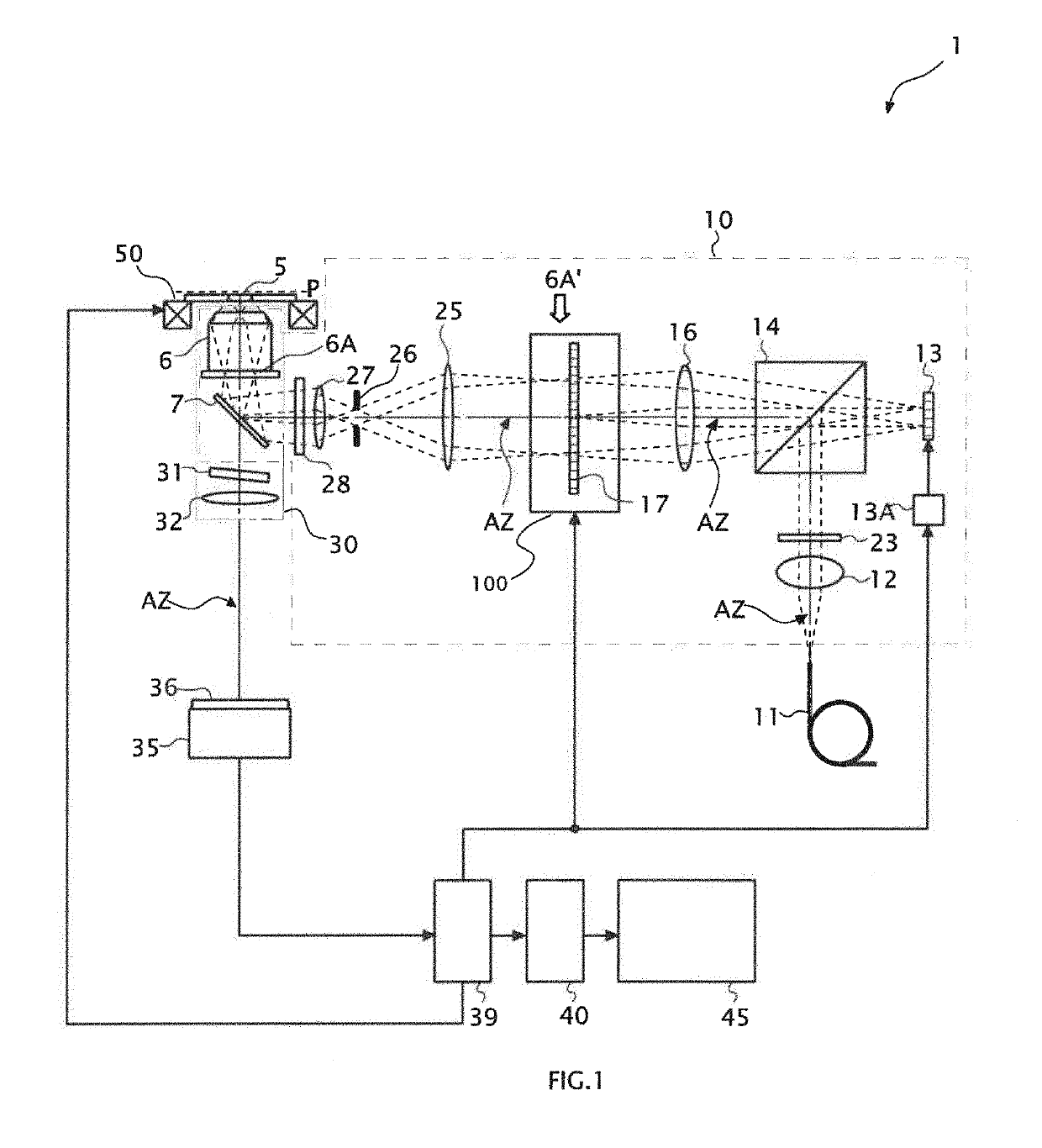
[0214]FIG. 21 is a configuration diagram of a 2D-SIM1′ (a structured illumination microscopy system 1) in this embodiment. In FIG. 21, the same reference numerals are supplied for the same component as ones illustrated in FIG. 1.

[0215]In the 2D-SIM1′ of this embodiment, two collecting lenses 61, 62 forming a relay lens are disposed in sequence between the dichroic mirror 7 and the objective lens 6, and a rotating Nipkow disk 70 is inserted in an image conjugate plane between the two collecting lenses 61, 62. A rotating mechanism 70A is provided at the rotating Nipkow disk 70. The rotating mechanism 70A rotates the rotating Nipkow disk 70 around a rotation shaft which is in parallel with the optical axis AZ, and deviated from the optical axis AZ. The controlling device 39 drives this rotatin...

third embodiment

[0222]Hereinafter, a modification example of the second embodiment is described as a third embodiment of the present invention. Here, only different points from the second embodiment are described.

[0223]FIG. 22 is a configuration diagram of a 2D-SIM1″ (a structured illumination microscopy system 1″) of this embodiment. In FIG. 22, the same reference numerals are supplied to the same components as ones illustrated in FIG. 21.

[0224]In this embodiment, a transmissive diffraction grating 13′ whose grating pattern is constant is used instead of the SLM 13 being a reflective diffraction grating whose grating pattern is variable, and both the modulating function and the demodulating function of the fluorescence image are supplied to the diffraction grating 13′. That is, in this embodiment, the demodulation of the modulated image is not performed by the image storing-calculating device 40 by means of calculation but optically performed by the diffraction grating 13′.

[0225]First, both laser ...


PUM

PropertyMeasurementUnit
angleaaaaaaaaaa
angleaaaaaaaaaa
refractive indexaaaaaaaaaa

Abstract

A structured illumination microscopy system including an illumination optical system illuminating excitation light to excite a fluorescent material contained in a sample on the sample with an interference fringe; a controlling part controlling a direction, a phase, and a spatial frequency of the interference fringe; an image-forming optical system forming an image of the sample which is modulated by illumination of the interference fringe; an imaging sensor capturing the image formed by the image-forming optical system; and a demodulating part performing demodulation processing by using a plurality of images captured by the imaging sensor in which the controlling part controls the spatial frequency of the interference fringe in accordance with an illuminating position of the interference fringe.

Description

CROSS-REFERENCE TO RELATED APPLICATION[0001]This application is a continuation application of International Application No. PCT / JP2015 / 002870, filed Jun. 8, 2015, designating the U.S., the entire contents of which are incorporated herein by reference.BACKGROUND1. Field[0002]The present application relates to a structured illumination microscopy system, a method, and a non-transitory storage medium storing program.2. Description of the Related Art[0003]A super-resolution microscopy is effective for observation of a specimen such as living cells. A structured illumination microscopy (SIM) being one kind of the super-resolution microscopies is a technology modulating information of a microstructure having high spatial frequency into a frequency capable of being transmitted to an image side of an objective lens by illuminating the specimen with an interference fringe (for instance, refer to Specification of U.S. Pat. No. 6,239,909). However, it turned out that an image quality of a supe...

Claims


Application Information

Patent Timeline
Patent Type & Authority Patents(United States)
IPC IPC(8): H04N7/18G01N21/64G02B21/36G02B21/00G02B27/58G02B21/16G02B21/08
CPCG02B21/082G01N21/64G02B21/16G02B21/361G01N21/6458G02B21/0056G02B21/0088G02B21/367G02B21/0076G02B21/0032G02B27/58
Inventor OUCHI, YUMIKO
Owner NIKON CORP
Why Eureka
Try Eureka