Powered end effector assembly with pivotable channel

a technology of end effector and pivoting channel, which is applied in the direction of gearing, surgical staples, medical science, etc., can solve the problems of difficult to provide a powered cartridge assembly capable of pivotal movement in relation to drive components of the body portion of the powered stapling device, and achieve the effect of facilitating pivotal movement of the channel

Active Publication Date: 2020-02-18
TYCO HEALTHCARE GRP LP
View PDF1514 Cites 357 Cited by
  • Summary
  • Abstract
  • Description
  • Claims
  • Application Information

AI Technical Summary

Benefits of technology

[0006]In one aspect of the disclosure an end effector includes a housing, an anvil assembly having a proximal end fixedly secured to the housing and a channel pivotally supported on the housing. The channel is pivotally supported in relation to the anvil assembly between spaced and approximated positions. A threaded lead screw is supported within the channel and an input shaft is rotatably supported within the housing. The input shaft has a proximal end supporting an input gear and a distal end coupled to a proximal end of the lead screw by a universal joint. The universal joint is configured to translate rotation of the input shaft into rotation of the lead shaft and to facilitate pivotal movement of the channel and the lead screw in relation to the input shaft and the housing.
[0018]In another aspect of the disclosure, a surgical stapling device includes a powered handle assembly, an adapter extending distally from the powered handle assembly, an end effector assembly supported on the distal end of the adapter. The end effector assembly includes a housing, an anvil assembly having a proximal end fixedly secured to the housing, and a channel pivotally supported on the housing. The channel is pivotal in relation to the anvil assembly between open and clamped positions. A threaded lead screw is supported within the channel and an input shaft is rotatably supported within the housing. The input shaft has a proximal end supporting an input gear and a distal end coupled to a proximal end of the lead screw by a universal joint. The universal joint is configured to translate rotation of the input shaft into rotation of the lead shaft and to facilitate pivotal movement of the channel and the lead screw in relation to the input shaft and the housing.
[0019]In embodiments, the end effector of the surgical stapling device includes a dynamic clamping member defining a threaded bore that receives the lead screw such that rotation of the lead screw effects longitudinal movement of the dynamic clamping member within the channel between a retracted position and an advanced position.

Problems solved by technology

Due to the complexities of known powered cartridge assemblies, it has proven difficult to provide a powered cartridge assembly capable of pivotal movement in relation to drive components of the body portion of the powered stapling device.

Method used


Image

  • Powered end effector assembly with pivotable channel
  • Powered end effector assembly with pivotable channel
  • Powered end effector assembly with pivotable channel

Examples


Embodiment Construction

[0041]Persons skilled in the art will understand that the devices and methods specifically described herein and illustrated in the accompanying drawings are non-limiting exemplary embodiments. It is envisioned that the elements and features illustrated or described in connection with one exemplary embodiment may be combined with the elements and features of another without departing from the scope of the present disclosure. As well, one skilled in the art will appreciate further features and advantages of the disclosure based on the above-described embodiments. Accordingly, the disclosure is not to be limited by what has been particularly shown and described, except as indicated by the appended claims.

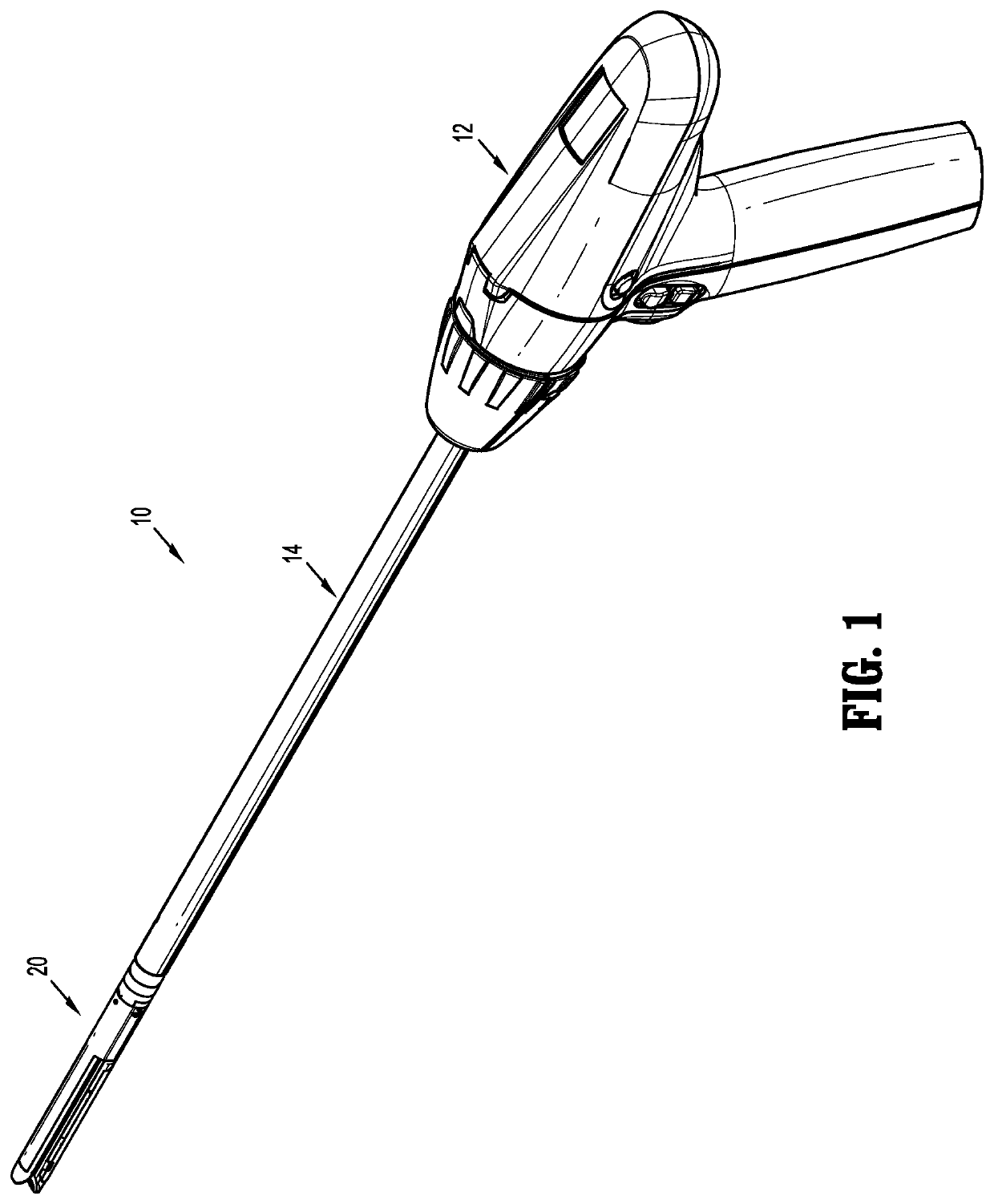
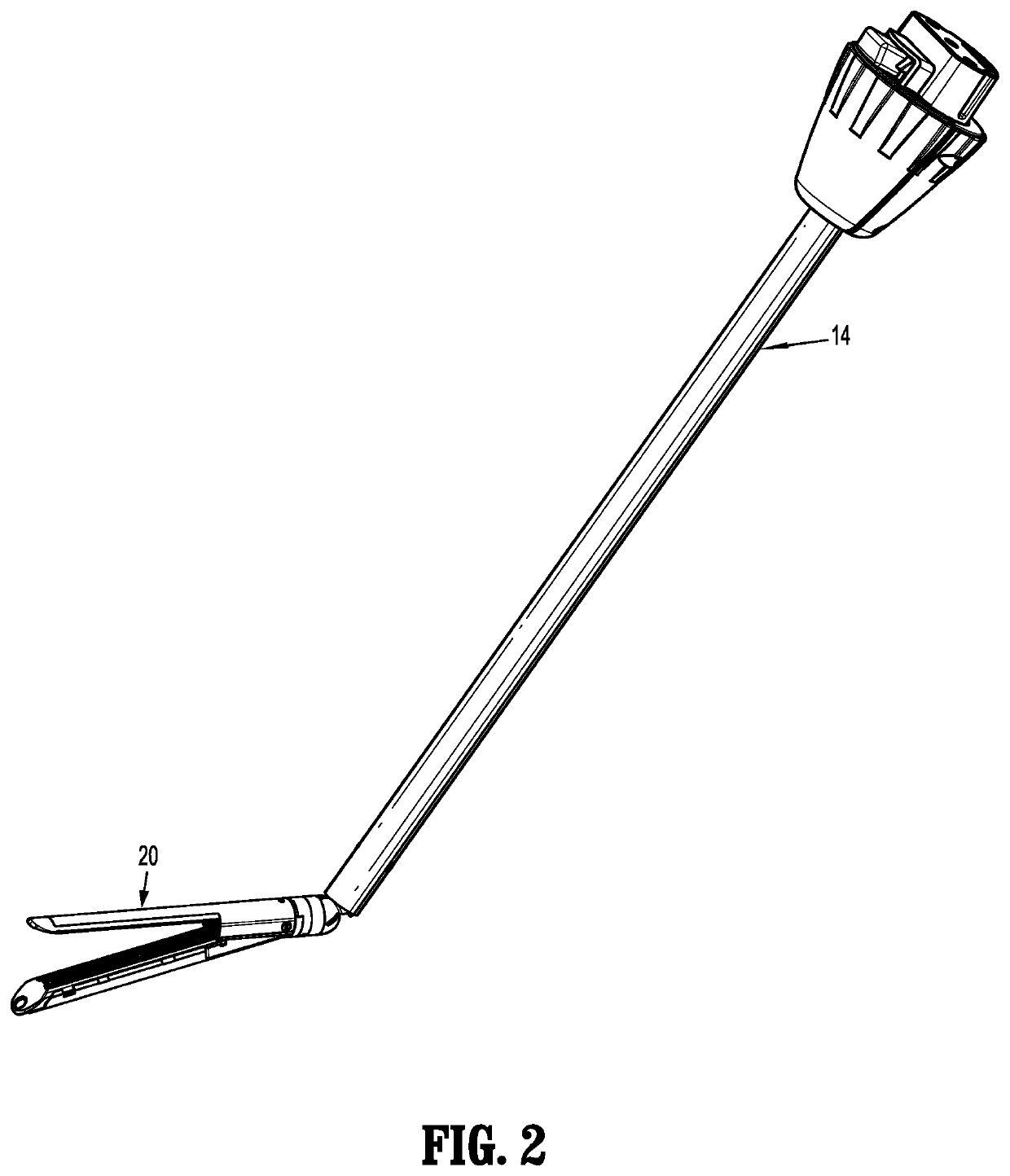
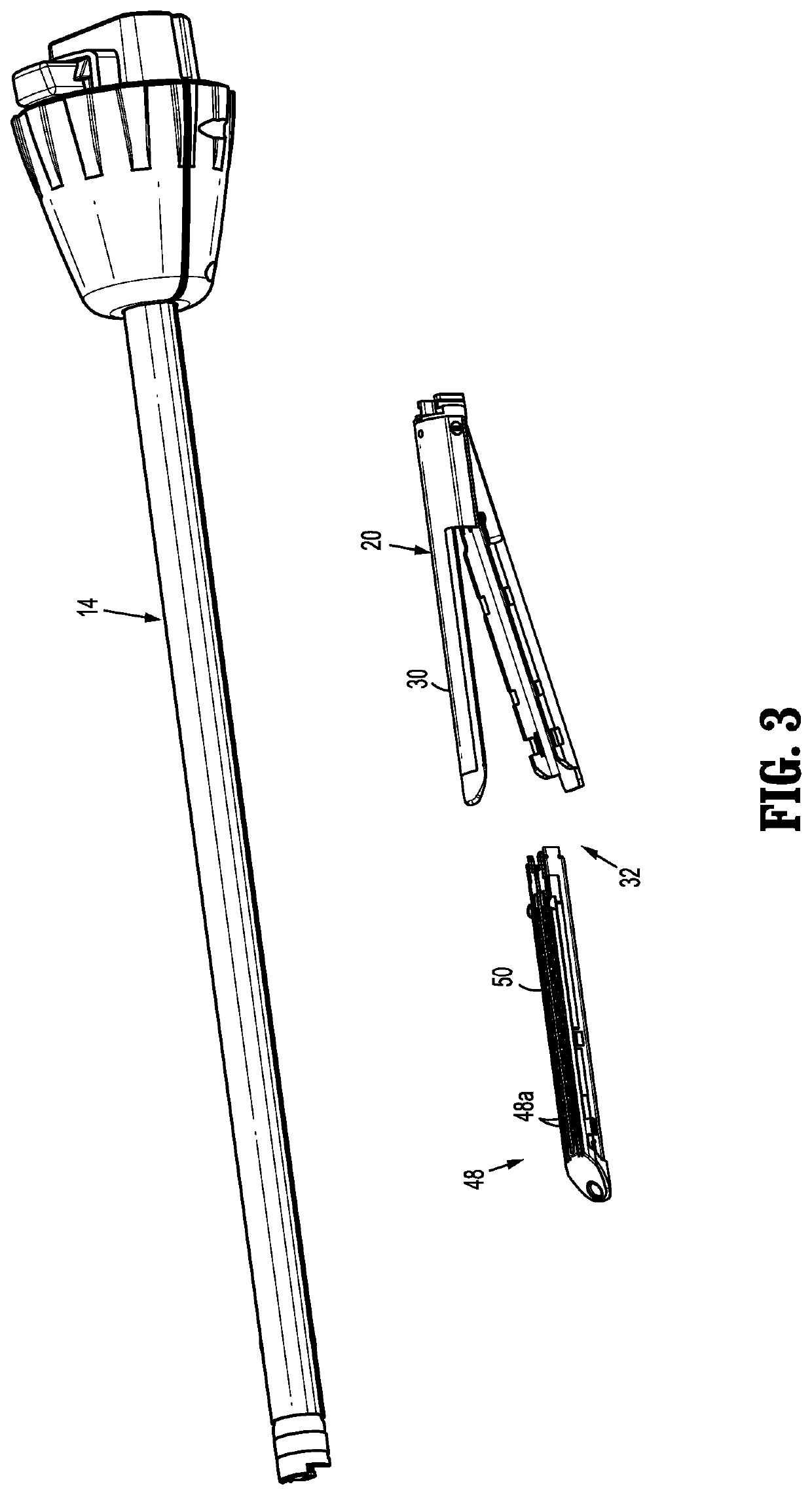
[0042]The present disclosure is directed to an end effector suitable for use with a powered surgical stapling device that includes a stationary or fixed anvil and a cartridge assembly that is supported for pivotal movement in relation to the anvil. In embodiments, the end effector incl...


PUM


Abstract

A powered surgical stapling device includes an end effector having a stationary anvil and a cartridge assembly that is supported for pivotal movement in relation to the anvil. In embodiments, the end effector includes a housing that supports an input shaft, an anvil fixedly supported on the housing, and a cartridge assembly pivotally supported in relation to the housing and the anvil. The cartridge assembly includes a channel that is pivotally supported on the housing. A lead screw is positioned within the channel and supports an internally threaded dynamic clamping member. The lead screw is secured to the input shaft by a universal joint such that rotation of the input shaft effects rotation of the lead screw and longitudinal translation of the dynamic clamping member along the lead screw. The universal joint facilitates the translation of the rotatable movement of the input shaft into rotation of the lead screw while allowing pivotal movement of the lead screw in relation to the input shaft.

Description

CROSS-REFERENCE TO RELATED APPLICATIONS[0001]This application claims the benefit of and priority to U.S. Provisional Patent Application Ser. No. 62 / 331,839, filed May 4, 2016, the entire disclosure of which is incorporated by reference herein.BACKGROUND1. Technical Field[0002]The present disclosure relates to an end effector assembly for use with a powered surgical stapling device. More specifically, the present disclosure relates to an end effector assembly for a powered linear stapling device having a pivotable cartridge assembly.2. Background of Related Art[0003]Surgical stapling devices for suturing tissue are well known in the surgical arts. These devices are available in a variety of configurations including linear and annular configurations. Typically, linear stapling devices include an end effector having a pair of jaws including a linear cartridge defining one or more rows of staples and an anvil that is movable from a position having one end spaced from the cartridge assem...

Claims


Application Information

Patent Timeline
Patent Type & Authority Patents(United States)
IPC IPC(8): A61B17/072F16D3/26F16H25/20A61B17/29A61B17/00
CPCA61B17/07207F16D3/265A61B2017/00845A61B2017/2927A61B2017/00473A61B2017/07278A61B2017/07257A61B2017/0069A61B2017/0046A61B2017/00477A61B2017/07285A61B2017/2931F16H25/20A61B2017/2903A61B2017/00734A61B2017/07214
Inventor BEARDSLEY, JOHN
Owner TYCO HEALTHCARE GRP LP
Why Eureka
Try Eureka