
Holding nozzle, holding head and transportation apparatus

a technology of holding head and holding nozzle, which is applied in the direction of lighting and heating apparatus, charging, furnaces, etc., can solve the problems of increasing the size affecting and increasing the weight of the suction head, so as to achieve no adverse effect on the quality of the display panel

Active Publication Date: 2020-02-18
HIRATA & CO LTD
View PDF28 Cites 1 Cited by
  • Summary
  • Abstract
  • Description
  • Claims
  • Application Information

AI Technical Summary

Benefits of technology

[0013]According to the present invention, the suction member including the suction portion is supported by the suction member support portion to be allowed to move with respect to the suction member support portion, and thus when the suction portion is brought into contact with the panel portion, only weight of the suction member including the suction portion is applied to the panel portion, and a downward force lowering the holding nozzle is not applied to the panel portion. That is, a large load is not applied to the panel portion via the suction portion in a direction in which a display surface is recessed, and thus distortion does not occur in the panel portion and there is no adverse effect on quality of the display panel.

Problems solved by technology

Accordingly, a downward force which lowers the holding nozzle is applied to the panel portion, and thus a downward load is applied to a portion of the display surface of the panel portion via the suction pad, and distortion occurs in the panel portion, which may adversely affect the quality of the display panel.
As a result, a size of the suction head increases, the weight thereof increases, and thus movement efficiency of the panel may be reduced.

Method used


Image

  • Holding nozzle, holding head and transportation apparatus
  • Holding nozzle, holding head and transportation apparatus
  • Holding nozzle, holding head and transportation apparatus

Examples


first embodiment

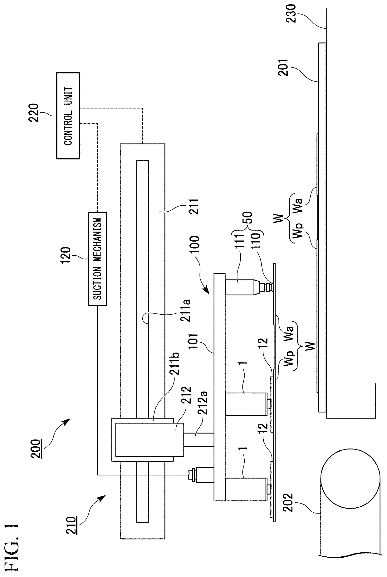
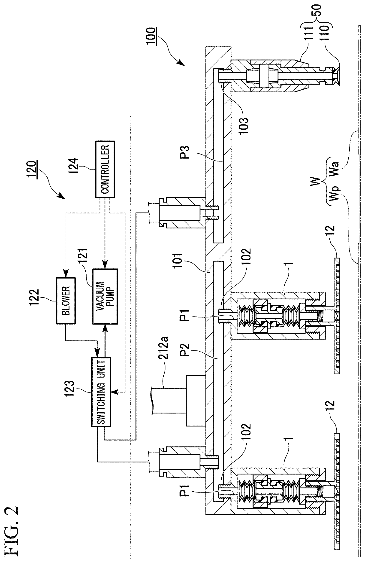
[0028]As shown in FIG. 1, each of holding nozzles 1 as a first embodiment of the present invention is mounted on a nozzle support member 101 of a holding head 100 in a transportation apparatus 200. The transportation apparatus 200 is an apparatus which transports a display panel assembly W such as a liquid crystal display or an organic EL display.

[0029]The transportation apparatus 200 includes a supply portion 230 to which a supply tray 201 on which a panel assembly W is placed is supplied, a holding head 100 for holding the panel assembly placed on the supply tray 201 supplied to the supply portion 230 as a supply section, a movement unit 210 for moving the holding head 100 to transfer the panel assembly W held by the holding head 100 to a conveyance unit 202 as a destination section, and a control unit 220 which controls a holding operation of the panel assembly by the holding head 100 and a movement operation of the holding head 100 by the movement unit 210. Here, the display pan...

modification example 1

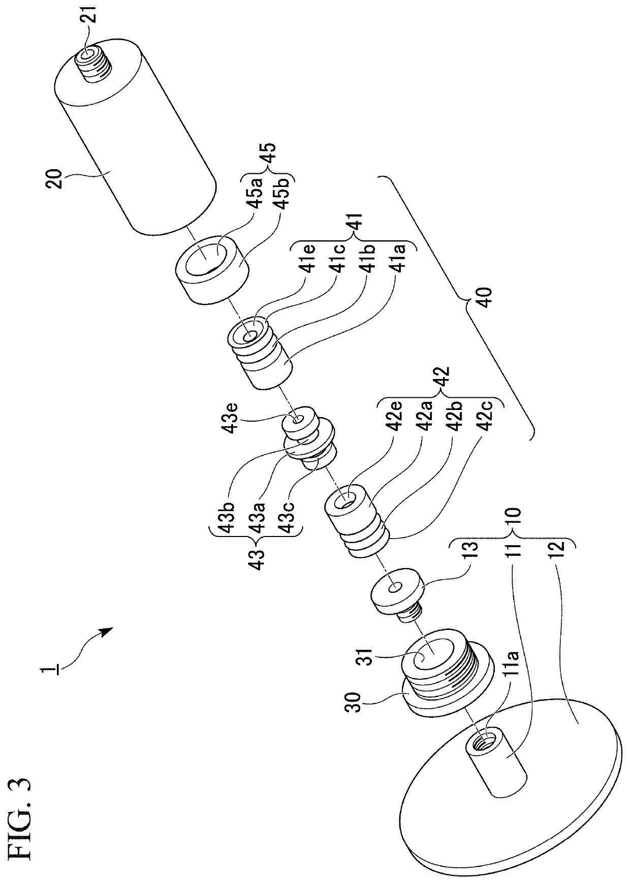
[0055]As shown in FIG. 7, in a holding nozzle 1A as a modification example of the first embodiment, a groove portion 20a is formed along an inner circumferential portion of the accommodation portion 20 in the circumferential direction. A holding member 46 is an annular body (for example, a snap ring) of which an outer diameter is larger than an inner diameter of the accommodation portion 20, an outer circumference of the annular body is fitted to the groove portion 20a, and the holding member 46 is mounted at a predetermined position inside the accommodation portion 20. An inner diameter of the holding member 46 is larger than an outer diameter of the base end portion 42a of the bellows pad portion 42 and is smaller than an outer diameter of the disk portion 43a, and by locking the disk portion 43a to the holding member 46, the communication member 40 passing through the inside of the holding member 46 is held at a predetermined position parallel in an axial direction in the accommo...

modification example 2

[0061]As shown in FIG. 8, in a holding nozzle 1B as a modification example of the first embodiment, the length of the communication member 40 is longer than the distance between the mouthpiece portion 13 and the negative pressure connection portion 21 when the suction portion 12 is moved forward with respect to the accommodation portion 20 and the mouthpiece portion 13 is positioned at the position separated from the negative pressure connection portion 21. Specifically, the communication member 40 is accommodated in the accommodation portion 20 in a state where the contractible portion 41b and the contractible portion 42b are slightly contracted. Accordingly, even when the mouthpiece portion 13 is positioned at the position separated from the negative pressure connection portion 21, the connection portion 41c is brought into contact with the negative pressure connection portion 21 and the connection portion 42c is brought into contact with the mouthpiece portion 13.

[0062]In order t...


PUM


Abstract

A holding nozzle is provided with a suction member including a suction portion which comes into contact with a panel and a shaft portion communicated with the suction portion, an accommodation portion in which the shaft portion is accommodated, a suction member support portion supporting the shaft portion such that the suction member is movable with respect to the accommodation portion, a negative pressure connection portion to which a negative pressure generator is connected, and a communication member accommodated in the accommodation portion between the negative pressure connection portion and the suction member support portion and has a hollow portion which is a portion of a flow path through which a fluid is flowed. The communication member includes a first connection portion connected to the negative pressure connection portion, a second connection portion connected to the shaft portion, and a contractible portion installed between the first and second connection portions.

Description

BACKGROUND OF THE INVENTIONField of the Invention[0001]Priority is claimed on Japanese Patent Application No. 2017-165887, filed on Aug. 30, 2017, the content of which is incorporated herein by reference.[0002]The present invention relates to a holding nozzle for holding a workpiece with suction of air, a holding head including the holding nozzle, and a transportation apparatus for transporting the workpiece held by the holding nozzle.Description of Related Art[0003]Conventionally, a workpiece such as a display panel assembly is moved using a holding nozzle with suction of air. Specifically, a suctioning disk-shaped suction pad that is an elastic member is pressed onto a flat portion of the workpiece to suck, the workpiece is held with suction by the suction pad, and then the workpiece is delivered from a supply section to a destination section.[0004]For example, Japanese Patent No. 3943481B2 discloses a holding nozzle including a suction pad portion, a bellows portion which is form...

Claims


Application Information

Patent Timeline
Patent Type & Authority Patents(United States)
IPC IPC(8): B25J15/06B65G47/91B65G49/06B25J15/00
CPCB65G49/061B25J15/0683B25J15/0052B65G47/917B65G47/918B65G2249/045B65G2201/02B23P19/00H05K13/02B65G47/91B65G2201/022
Inventor KAWAMOTO, YUKIHIROSUGAYA, SATOSHI
Owner HIRATA & CO LTD
Learn More