Supercharge Your Innovation With Domain-Expert AI Agents!

Vehicle air drag reducing apparatus and method of use thereof

a technology of air drag and reducing apparatus, which is applied in the direction of vehicle components, road transportation emission reduction, vehicle body streamlining, etc., can solve the problems of air drag, turbulence and drag, poor visibility, etc., and achieve the effect of reducing aerodynamic drag, reducing aerodynamic drag, and reducing aerodynamic drag

Active Publication Date: 2020-02-25
TRANSTEX LLC
View PDF217 Cites 6 Cited by
  • Summary
  • Abstract
  • Description
  • Claims
  • Application Information

AI Technical Summary

Benefits of technology

An aspect of our work, in accordance with at least one embodiment thereof, provides an automatically retractable aerodynamic air drag reducing apparatus adapted to be installed on a trailer to reduce the aerodynamic drag produced by the movement of the trailer when pulled by a vehicle.
An aspect of our work, in accordance with at least one embodiment thereof, provides an aerodynamic air drag reducing apparatus adapted to be installed on a trailer to reduce the aerodynamic drag produced by the movement of the trailer when pulled by a vehicle that can be swayed-away between a trailer door-opening configuration and an aeronautical configuration.
An aspect of our work, in accordance with at least one embodiment thereof, provides an aerodynamic air drag reducing apparatus adapted to be installed on a trailer to reduce the aerodynamic drag produced by the movement of the trailer when pulled by a vehicle that has an optimized panels geometry and intervening angles thereof.
An aspect of our work, in accordance with at least one embodiment thereof, provides a retractable aerodynamic air drag reducing apparatus that can be universally, easily installed and economically manufactured.

Problems solved by technology

It is known that a significant amount of air drag results when a vehicle travels over a roadway; this is due to an area of low pressure created at the rear end of the vehicle.
For example, with a tractor-trailer type vehicle, the air makes a sharp bend around the squared-off back of the trailer, thus causing turbulence and drag.
Furthermore, the turbulence also causes poor visibility in rainy conditions and an accumulation of dirt on the back of trailers.
Therefore, the addition of aerodynamic device, such as a rear deflector, diminishes the air drag and results in lower fuel consumption.
However, in this drag apparatus, the ram construction does not enable the doors to be moved between a closed position to a completely opened position where the doors are adjacently parallel to the sides of the trailer vehicle.

Method used


Image

  • Vehicle air drag reducing apparatus and method of use thereof
  • Vehicle air drag reducing apparatus and method of use thereof
  • Vehicle air drag reducing apparatus and method of use thereof

Examples


Embodiment Construction

A preferred embodiment of the present invention is described below with reference to the drawings.

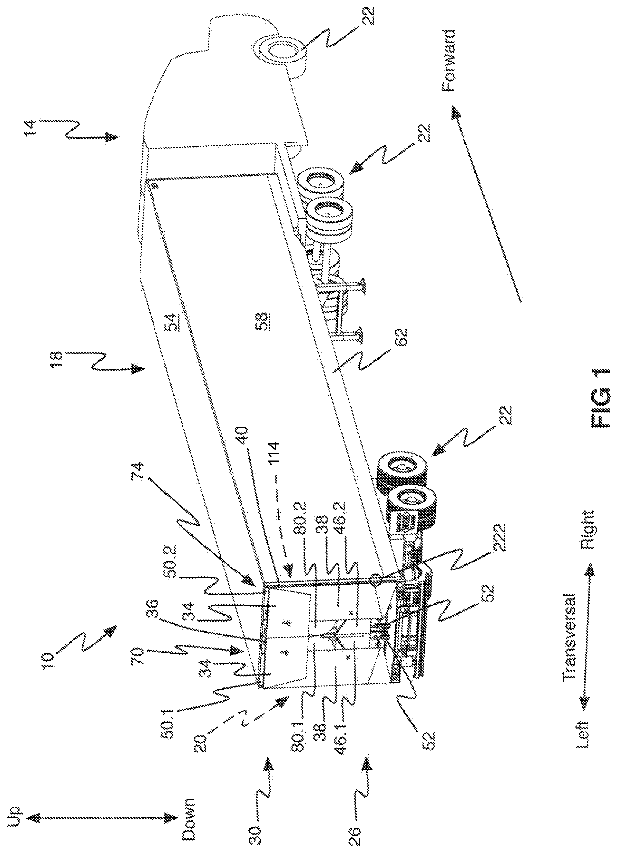
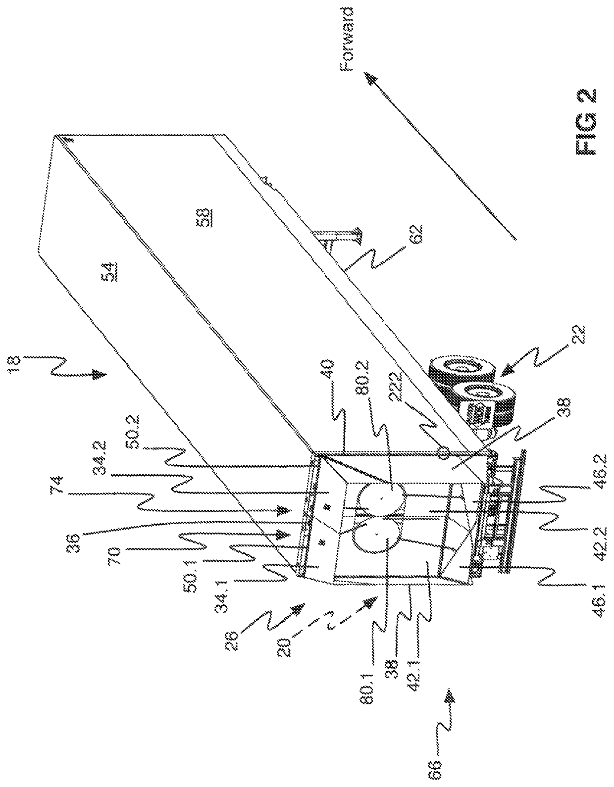
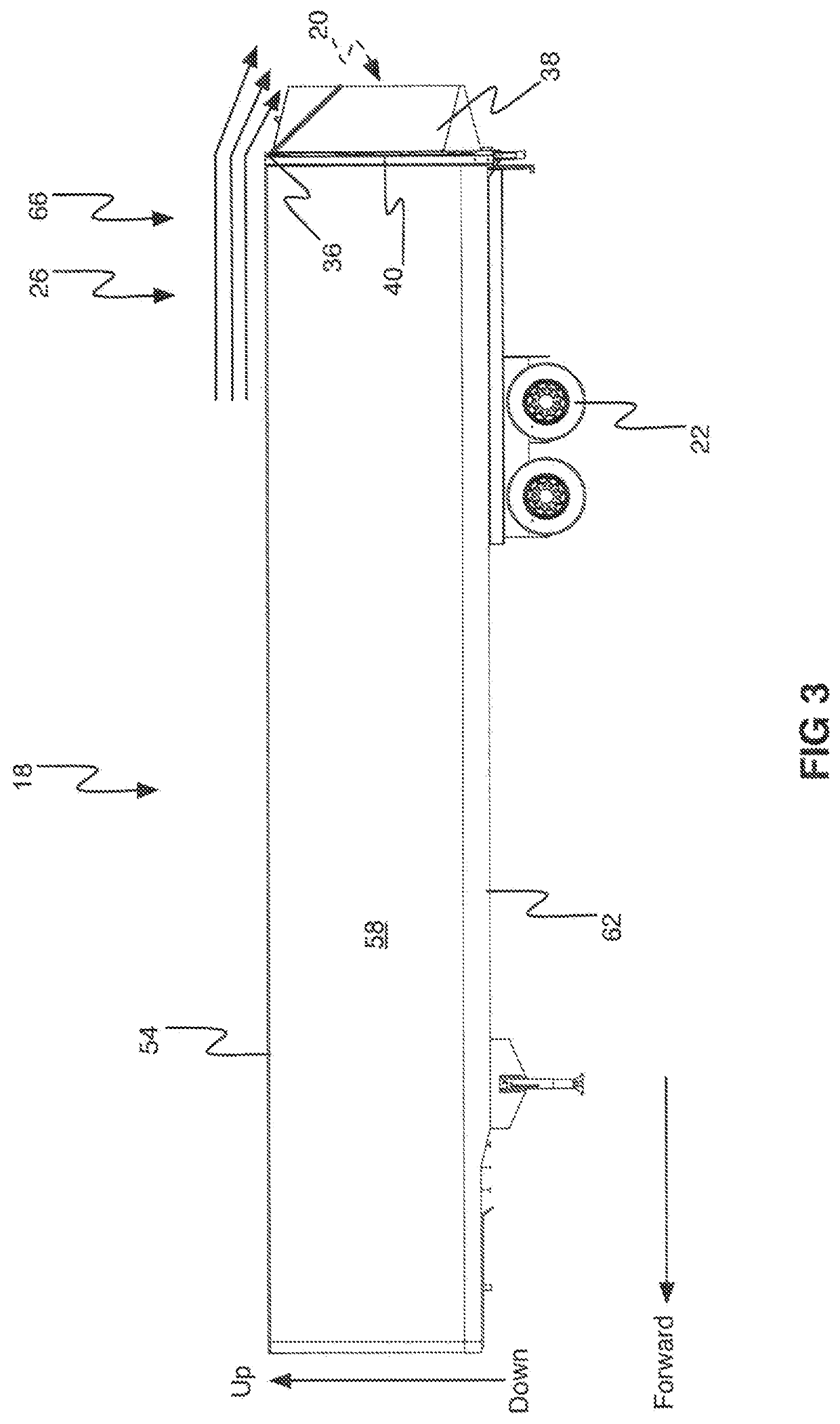
A vehicle 10 including a tractor 14 and a trailer 18 is illustrated in FIG. 1. The tractor 14 is operatively connected to the trailer 18 to pull the trailer 18 in a forward direction. The tractor 14 and the trailer 18 are equipped with a series of wheels 22 to propel and support the vehicle 10 with optional cargo therein. The trailer 18 is equipped with a retractable aerodynamic air drag reducing apparatus 26 (hereinafter RAADRA 26) over a rear surface 20 of the trailer 18 as illustrated in its retracted configuration 30. The RAADRA 26 is deployable in an expanded configuration and retractable in a retracted configuration on a basis of specific vehicle 10 speeds, as it will be described in detail below. The RAADRA 26 includes a top panel 34 (of which a left top panel is identified 34.1 and a right top panel is identified 34.2, both are visible, inter alia, in FIG. 2), a pair of side pan...


PUM


Abstract

This invention relates to a retractable aerodynamic air drag reducing apparatus for reducing the air drag of a vehicle, the retractable aerodynamic air drag reducing apparatus being adapted to move between an expanded configuration and a retracted configuration on a basis of a signal from the vehicle.

Description

CROSS-REFERENCEThe present application relates to and is a non-provisional application of U.S. provisional application No. 62 / 464,130 filed Feb. 27, 2017 entitled VEHICLE AIR DRAG REDUCING APPARATUS AND METHOD OF USE THEREOF, this document is incorporated herein by reference in its entirety.FIELD OF THE INVENTIONThis invention relates to an aerodynamic drag reducing apparatus adapted to be mounted on a rear portion of a trailer to improve the aerodynamic efficiency of the trailer. The present invention more precisely relates to a vehicle retractable drag-reducing apparatus.BACKGROUND OF THE INVENTIONRoad tractors are generally used to pull trailers on roads to transport cargo. Aerodynamic apparatuses can be installed on the road tractor and / or on the trailer in order to reduce the aerodynamic air drag and improve fuel efficiency.Rear drag-reducing apparatuses are generally installed and secured to a rear portion of a trailer to help manage the flow of air behind the trailer. It is k...

Claims


Application Information

Patent Timeline
Patent Type & Authority Patents(United States)
IPC IPC(8): B62D35/00
CPCB62D35/001B62D35/007B62D37/02Y02T10/82
Inventor BOIVIN, MATHIEUDAOUST, SYLVAINDEIR, WALIDBASSILY, GEORGEJAHROMI, ALI FELLAHDESOURDY, GUILLAUME
Owner TRANSTEX LLC
Features
  • R&D
  • Intellectual Property
  • Life Sciences
  • Materials
  • Tech Scout
  • Unparalleled Data Quality
  • Higher Quality Content
  • 60% Fewer Hallucinations
Learn More