
Epicardial mapping

a mapping and epidural technology, applied in the field of epidural mapping, can solve the problems of distortion in the spatial representation of measurements, observer inability to see the results produced, and electroanatomic maps based on fam-produced volumes are misleading

Active Publication Date: 2020-03-03
BIOSENSE WEBSTER (ISRAEL) LTD
View PDF34 Cites 0 Cited by
  • Summary
  • Abstract
  • Description
  • Claims
  • Application Information

AI Technical Summary

Benefits of technology

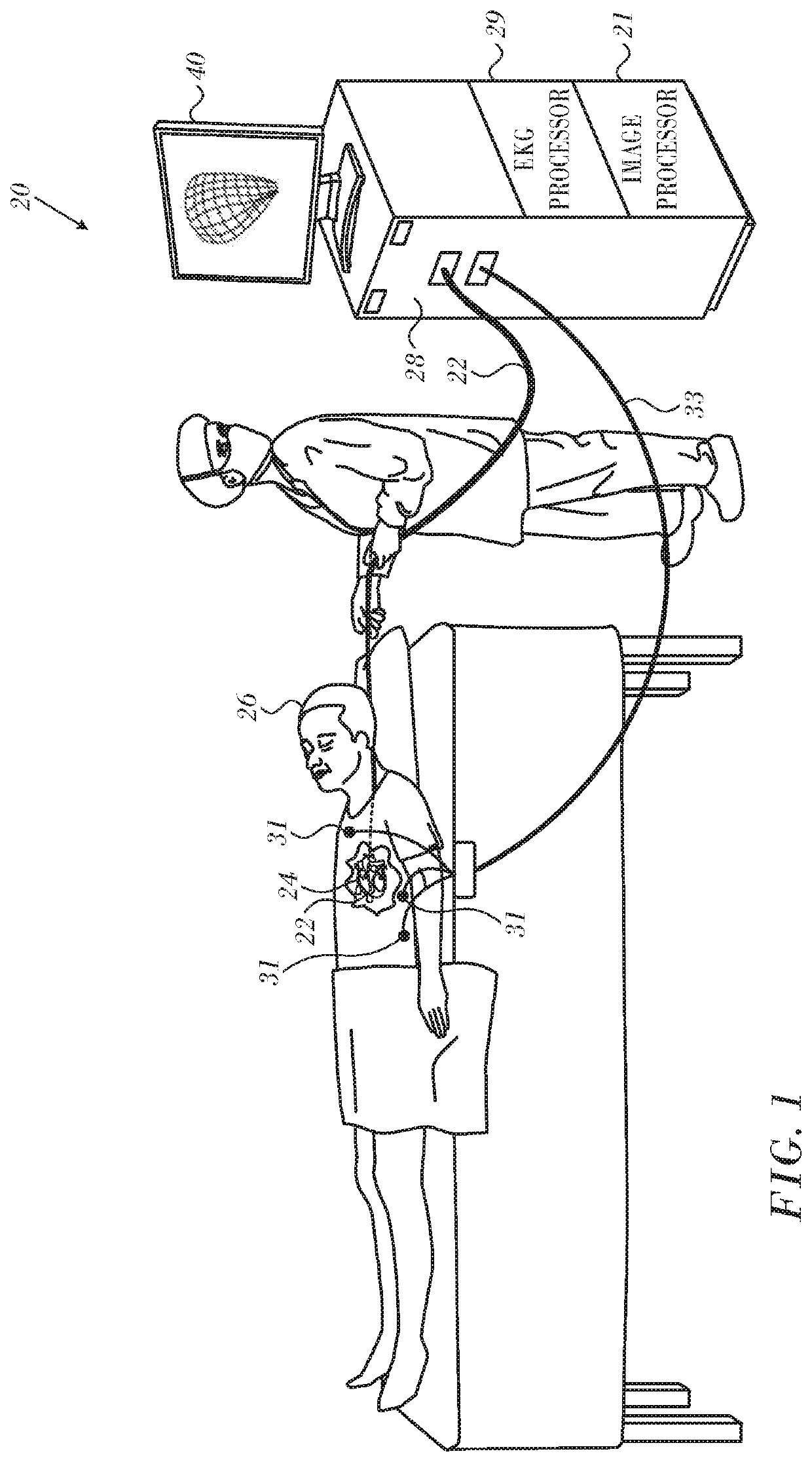
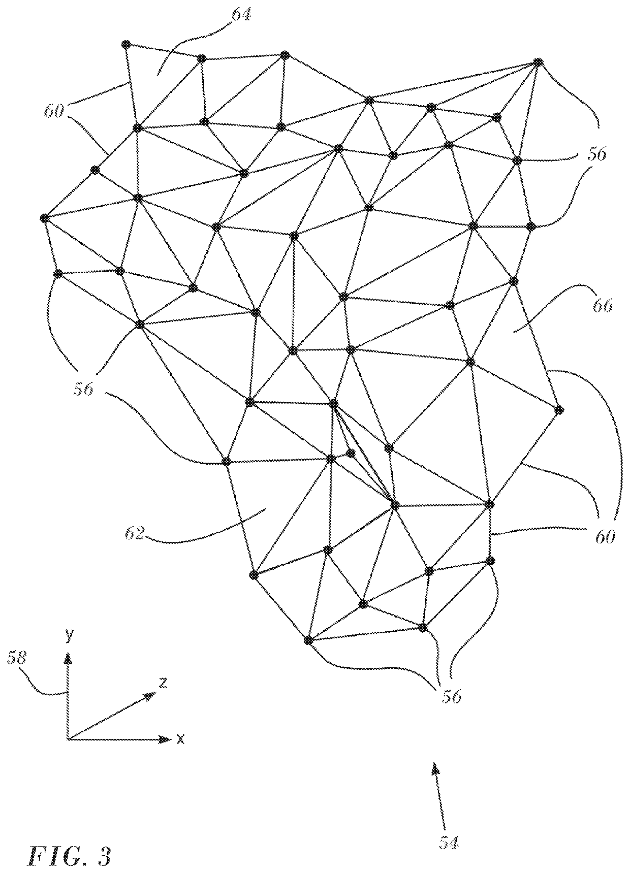
The patent describes a method and apparatus for generating a 3D image of the heart's epicardial surface. The method involves acquiring electrical signals from the heart and creating a closed 3D image of the heart using ultrasound imaging. The image is then modeled as a mesh of triangles, with front-facing and rear-facing triangles. The method also involves placing the acquired locations in registration with the mesh and displaying the electroanatomic data on the appropriate triangles. The technical effect of this patent is to provide a more accurate and complete representation of the heart's epicardial surface.

Problems solved by technology

This produces distortion in the spatial representation of the measurements.
Moreover, besides containing spatial errors, electroanatomic maps based on the FAM-produced volume are misleading.
Thus, the observer cannot see the results produced by measurements taken at points that map to the rear-facing portions of the shape and sees only results relating to front-facing points.

Method used


Image

  • Epicardial mapping
  • Epicardial mapping
  • Epicardial mapping

Examples


first embodiment

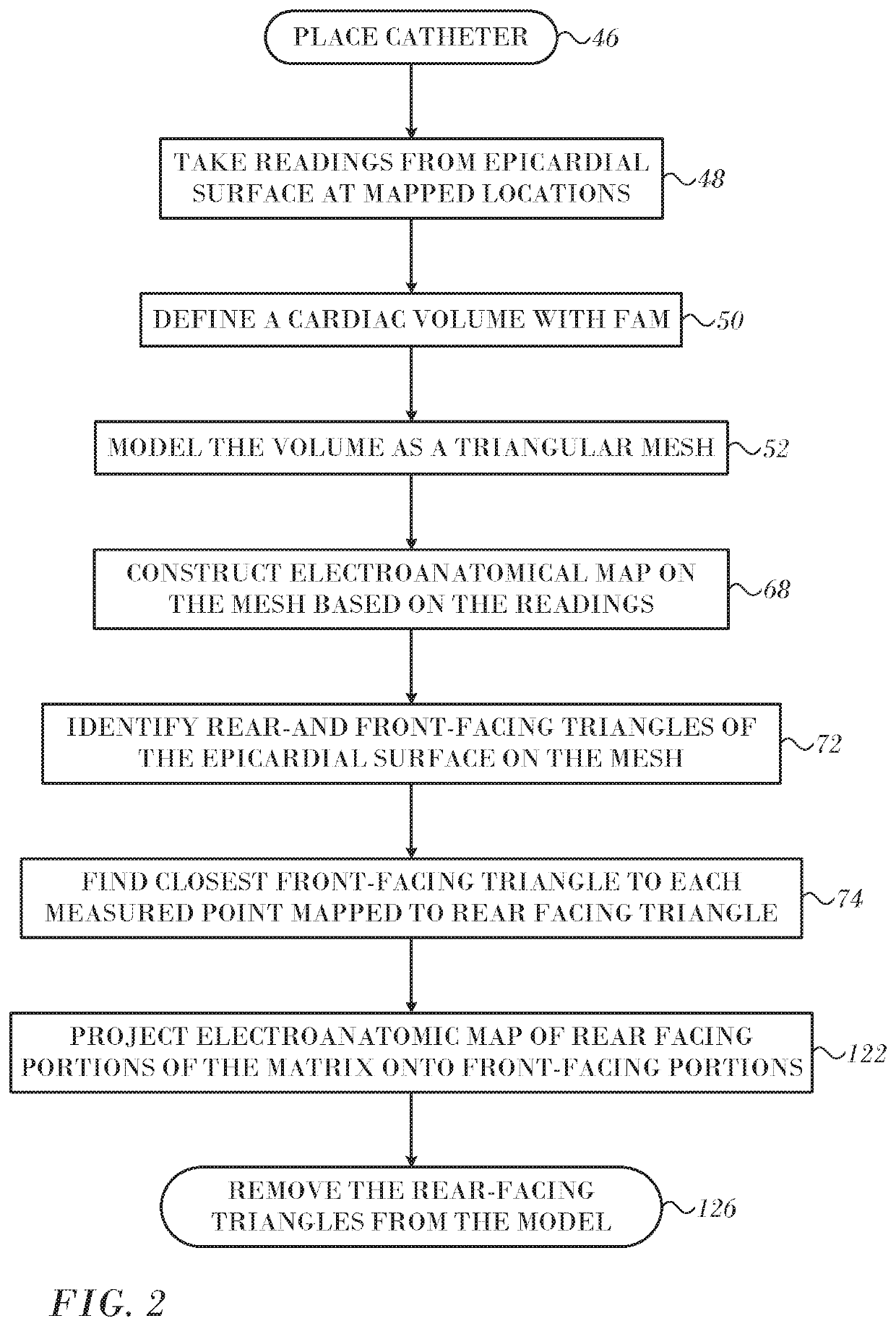
[0037]Reference is now made to FIG. 2, which is a flow chart of a method of electroanatomic mapping of the epicardium in accordance with an embodiment of the invention. The process steps are shown in a particular linear sequence in FIG. 2 for clarity of presentation. However, it will be evident that many of them can be performed in parallel, asynchronously, or in different orders. Those skilled in the art will also appreciate that a process could alternatively be represented as a number of interrelated states or events, e.g., in a state diagram. Moreover, not all illustrated process steps may be required to implement the method.

[0038]At initial step 46 a mapping catheter is positioned at the epicardium. At step 48 electrical readings are at mapped locations are taken as described above.

[0039]At step 50 a closed 3-dimensional image representing a cardiac volume is generated using the above-described FAM technique. Then, at step 52 the epicardial surface, including the mapped location...

second embodiment

[0052]Typically an FAM-produced volume is generated and during the patient session in which epicardial readings are taken. In this embodiment the FAM-produced volume is generated from images pre-acquired at a different time from the epicardial readings. The locations of the epicardial readings are then placed in registration with the FAM-produced volume by known methods, for example the methods described in commonly assigned U.S. Patent Application Publication Nos. 20130123773 entitled Integrative Atrial Fibrillation Ablation, 20160354049 entitled Registration of Coronary Sinus Catheter Image and 20160120426 entitled Registration Maps Using Intra-Cardiac Signals, all of which are herein incorporated by reference. The process described in the discussion of FIG. 2 beginning with step 52 can then be performed using the FAM-produced volume.

Implementation Details.

[0053]Reference is now made to FIG. 10, which is a schematic diagram of an ablation and active current location (ACL) circuit ...


PUM


Abstract

Electroanatomic mapping of the epicardium includes acquiring first and second electroanatomic data from first and second epicardial locations, acquiring a closed 3-dimensional image of the epicardium and modeling the image as a 3-dimensional triangular mesh. The first and second locations align with front-facing triangles and rear-facing triangles of the mesh. The second locations are projected from the rear-facing triangles onto the closest front-facing triangles. The first and second electroanatomic data are displayed on the front-facing triangles and the closest front-facing triangles, respectively.

Description

COPYRIGHT NOTICE[0001]A portion of the disclosure of this patent document contains material that is subject to copyright protection. The copyright owner has no objection to the facsimile reproduction by anyone of the patent document or the patent disclosure, as it appears in the Patent and Trademark Office patent file or records, but other-wise reserves all copyright rights whatsoever.BACKGROUND OF THE INVENTION1. Field of the Invention[0002]This invention relates to detecting, measuring or recording bioelectric signals of the body. More particularly, this invention relates to analysis of electrical signals of the heart for diagnostic purposes.2. Description of the Related Art[0003]The meanings of certain acronyms and abbreviations used herein are given in Table 1.[0004]TABLE 1Acronyms and AbbreviationsLATLocal Activation TimePDMPotential Duration MapFAMFast Anatomical Mapping[0005]Epicardial mapping of the wall of the heart to obtain functional electroanatomic maps of the external ...

Claims


Application Information

Patent Timeline
Patent Type & Authority Patents(United States)
IPC IPC(8): A61B5/044A61B18/00G06T15/04A61B8/12A61B18/14A61B5/04A61B5/042A61B5/06A61B5/296
CPCA61B5/063A61B5/04011A61B5/0422A61B18/1492G06T15/04A61B8/12A61B5/044A61B5/04012A61B2018/00577A61B2562/0209G06T2210/41A61B2018/00839A61B5/283A61B5/341A61B5/316A61B5/287A61B5/339
Inventor TURGEMAN, AHARONCOHEN, BENJAMIN
Owner BIOSENSE WEBSTER (ISRAEL) LTD
Learn More