Robotic mobility device and control

Active Publication Date: 2020-03-03
IKUTUKI
View PDF20 Cites 32 Cited by
  • Summary
  • Abstract
  • Description
  • Claims
  • Application Information

AI Technical Summary

Benefits of technology

[0029]Features of the invention include: (1) A postural data-pool stored with calculated results of joints angle, joint relative coordinate, velocity and overturn load capacity, movement index, energy conservation level, statics and dynamics characteristics of specific user limbs length and weight. The calibrated posture data is used as initial values for the robotic mobility assistant device's bipedal ambulation control. (2) N-particles movement simulation, dynamic data, joint energy timing, and torsional capacity afford fluent bipedal ambulation and fall prevention. (3) An algorithm provides analysis capacity for calculating current balance state and predicting possible near future imbalanced states. The algorithm also implements warning and process to recover in the event of an emergency. (4) The robot is designed with vertical load carrying capacity and horizontal stability by posture configuration with torsional timing control cables providing lateral mobility to counter horizontal load impact. (5) Joints are connected to rigidity control devices (bead-filled vacuum compartments). Negative pressure causes the bead-filled structures to form passive rigid compression elements that stiffen the joints and prevents excessive rotational movement, at given angles, of the connected frames to supplement holding capacity of electric powered motors. (6) Air pump systems operate in coordination with a user's joint movements; they apply an air pressure difference in airtight vacuum chambers that are located inside the robotic device's frame member walls. (7) The spring sets and joint rotation lock are energy timed to and synchronized with the user's dynamic requirements so as to optimize energy conversion between elastic energy, kinetic energy and potential energy during motion. (8) Accumulated torsional spring energy, which is generated from a set of bipedal ambulation patterns, is a potential energy source, in addition to bending energy, further increase system efficiency. (9) Sensor systems which include, for example, inclinometer sensors, accelerometers, camera sensors, and infrared sensors apply vertical edges in the environment data. Information plus edge pressure sensors in

Problems solved by technology

Moreover, the person using the exoskeleton has limited control of

Method used


Image

  • Robotic mobility device and control
  • Robotic mobility device and control
  • Robotic mobility device and control

Examples


Embodiment Construction

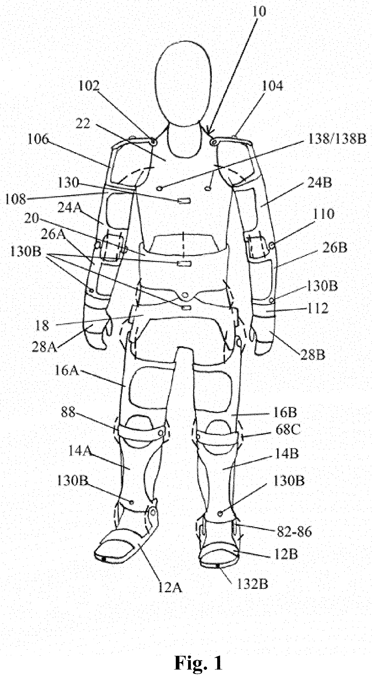
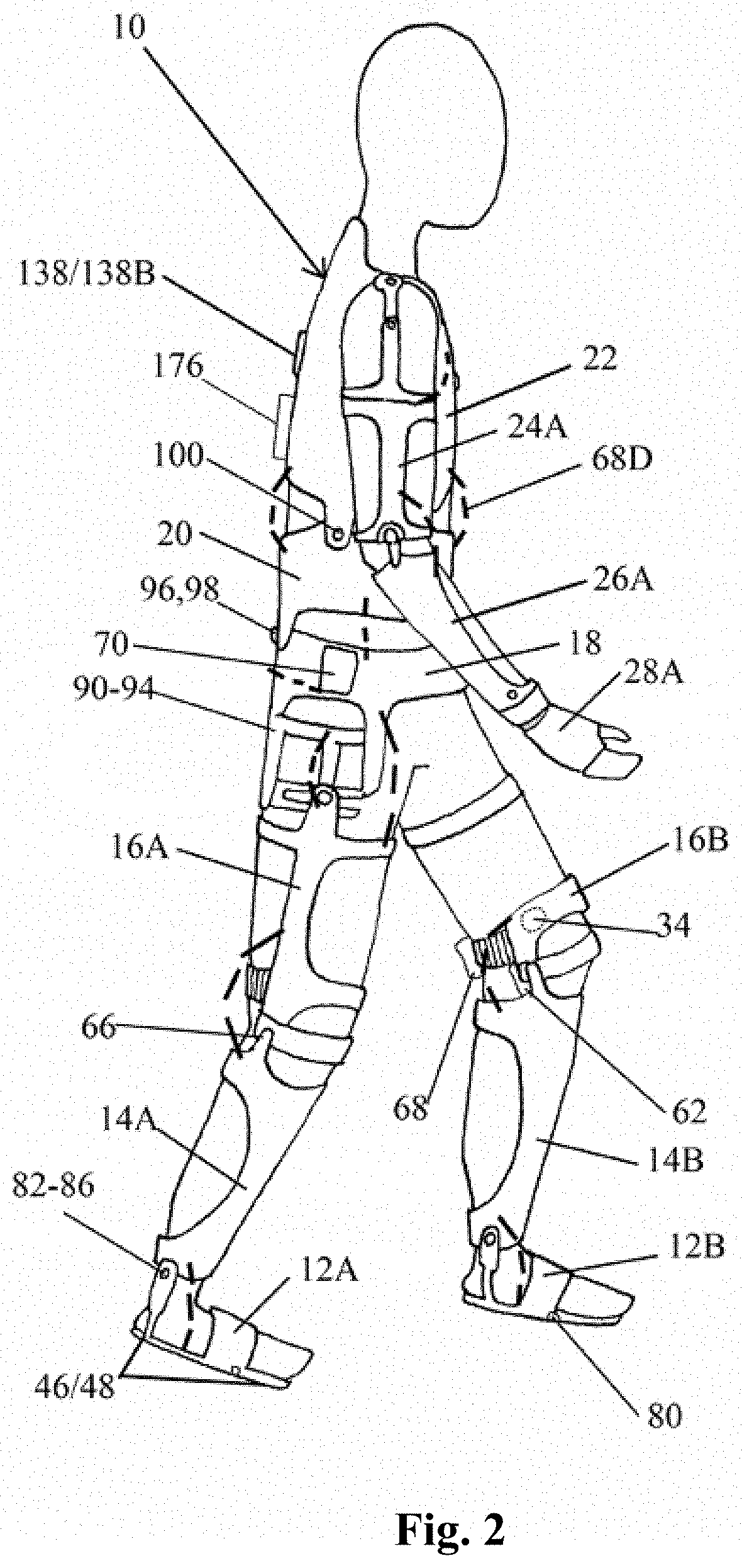
[0068]FIGS. 1 and 2 depict a robotic mobility assistant device, as worn by a person that includes a plurality of frame elements 10 to 28 that are interconnected by mechanical joints 80 to 112. Each joint device can exhibit different degrees of freedom, as further shown in FIG. 4, that are similar to a person's walking and moving degrees of freedom. The frame components include: foot frames 12A,12B, shin frames 14A,14B, thigh frames 16A,16B, hip base frame 18, abdomen frame 20, chest frame 22, upper arm frames 24A 24B, forearm frames 26A, 26B, and palm frames 28A,28B. The hip, abdomen, and chest frame form the torso or truck frames, the foot, shin, and thigh frames form the lower limb frames, and the upper arm, forearm and palm frames form the upper limb frames.

[0069]The frame elements 12-18 are constructed of materials that are sufficiently rigid to support the individual. Suitable materials include, for example, high strength, carbon fiber, metals such as aluminum alloys, fiberglas...


PUM


Abstract

Robotic mobility assistant exoskeleton with frame members, which are attached adjacent to biological joints, supplements relative movement between skeletal members. Mechanical joint defines a center of relative rotation of frame members about three mutually perpendicular axes with the center of relative rotation of frame members being displaced from the outer surfaces of skeletal members to correspond in position with the center of biological joint. Actuation devices including powered cable springs rotate frame members. Control system executes calibrated user specific posture sequences and activates power. Mechanical joint exhibits cylindrical guide surfaces defining a slidable or rotatable connection of frame members and has a radius intersecting the center of the biological joint. Node control network distributes computing load and reduces communications overhead. Map unit has object recognition system for monitoring environment. Standard posture data derived from rules of ambulation and posture provide positioning control, optimized by energy-timed margins for balance maintenance.

Description

REFERENCE TO RELATED APPLICATIONS[0001]This application claims priority under 35 U.S.C. § 119(e) to application No. 62 / 319,791 filed Apr. 8, 2016, which is incorporated herein by referenceFIELD OF THE INVENTION[0002]The present invention generally relates to techniques for supplementing relative movement between two or more substantially rigid biological skeletal members, such as limbs, that are coupled at a biological joint and in particular to a human exoskeleton that includes frame members and associated rigidity control devices.BACKGROUND OF THE INVENTION[0003]Robotics has been developed to assist people to walk. Current exoskeleton systems require a walking aid to function. Moreover, the person using the exoskeleton has limited control of such systems and thus the user's mobility and range are restricted.SUMMARY OF THE INVENTION[0004]The present invention is directed to a bipedal, powered ambulatory robot for mobility assistance and to ambulation control. The ambulatory robot i...

Claims


Application Information

Patent Timeline
IPC IPC(8): A61H3/00A61F5/01B25J9/00A61F5/02A61F2/72A63B71/12
CPCA61F5/0102B25J9/0006A63B71/1225A61F2/72A61F2005/0144A61H2201/1602B25J9/104
Inventor CHOU, WENPEICHOU, DA JIUN
Owner IKUTUKI
Why Eureka
Try Eureka