Device for tapping electrical energy from hydropower

a technology for hydropower and electric energy, applied in the direction of motors, electrical devices, control systems, etc., can solve the problems of comparatively inflexible plant application capabilities, comparatively complex and intricate installation of plants, and inaccurate blade guiding in water conveying ducts, so as to improve water guiding, improve the effect of energy conversion and increase the efficiency of plants

Inactive Publication Date: 2015-07-30
WRH WALTER REIST HLDG
View PDF14 Cites 3 Cited by
  • Summary
  • Abstract
  • Description
  • Claims
  • Application Information

AI Technical Summary

Benefits of technology

[0011]It is therefore an object of the present invention to optimize the guiding of the flow-impinged components in the water conveying duct and also to improve the water guiding in general and also to optimize the energy conversion so as to increase the efficiency of the plant at the very least. In addition, the plant is to be able to be installed in a quick and simple manner at site.

Problems solved by technology

The plant is comparatively inflexible with regard to its application capabilities since this can only be designed together with a vertical chute.
The described solution has the disadvantage that the blade guiding in the water conveying duct is rather inaccurate so that the receiving compartments are too permeable in the movement direction for the water being carried along and some of the water being carried along flows down the water conveying duct to the outlet region without being utilized.
In addition, the installation of the plant is also comparatively complex and intricate.
Furthermore, the energy conversion is not implemented in an optimum manner.

Method used


Image

  • Device for tapping electrical energy from hydropower
  • Device for tapping electrical energy from hydropower
  • Device for tapping electrical energy from hydropower

Examples


Embodiment Construction

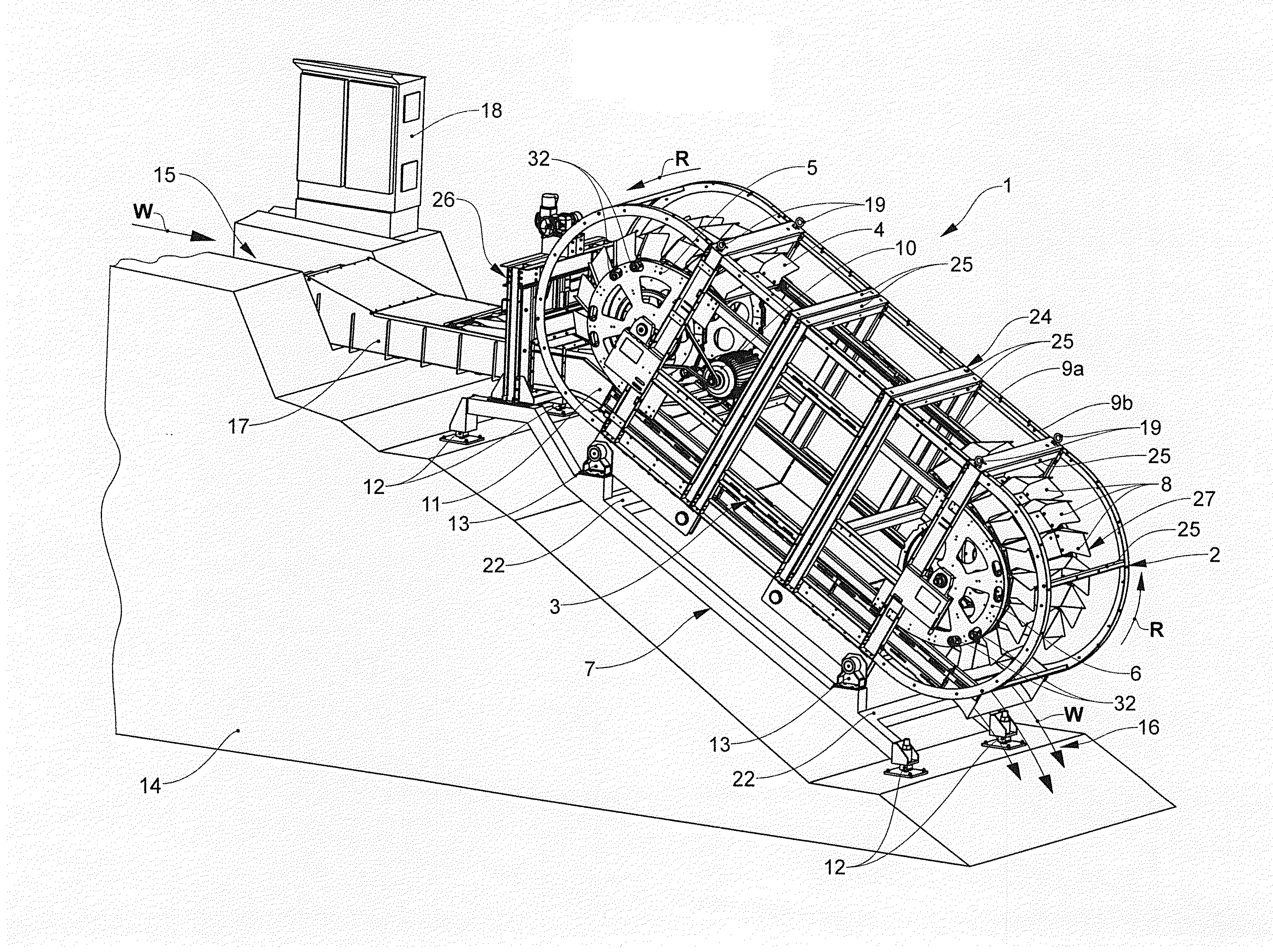
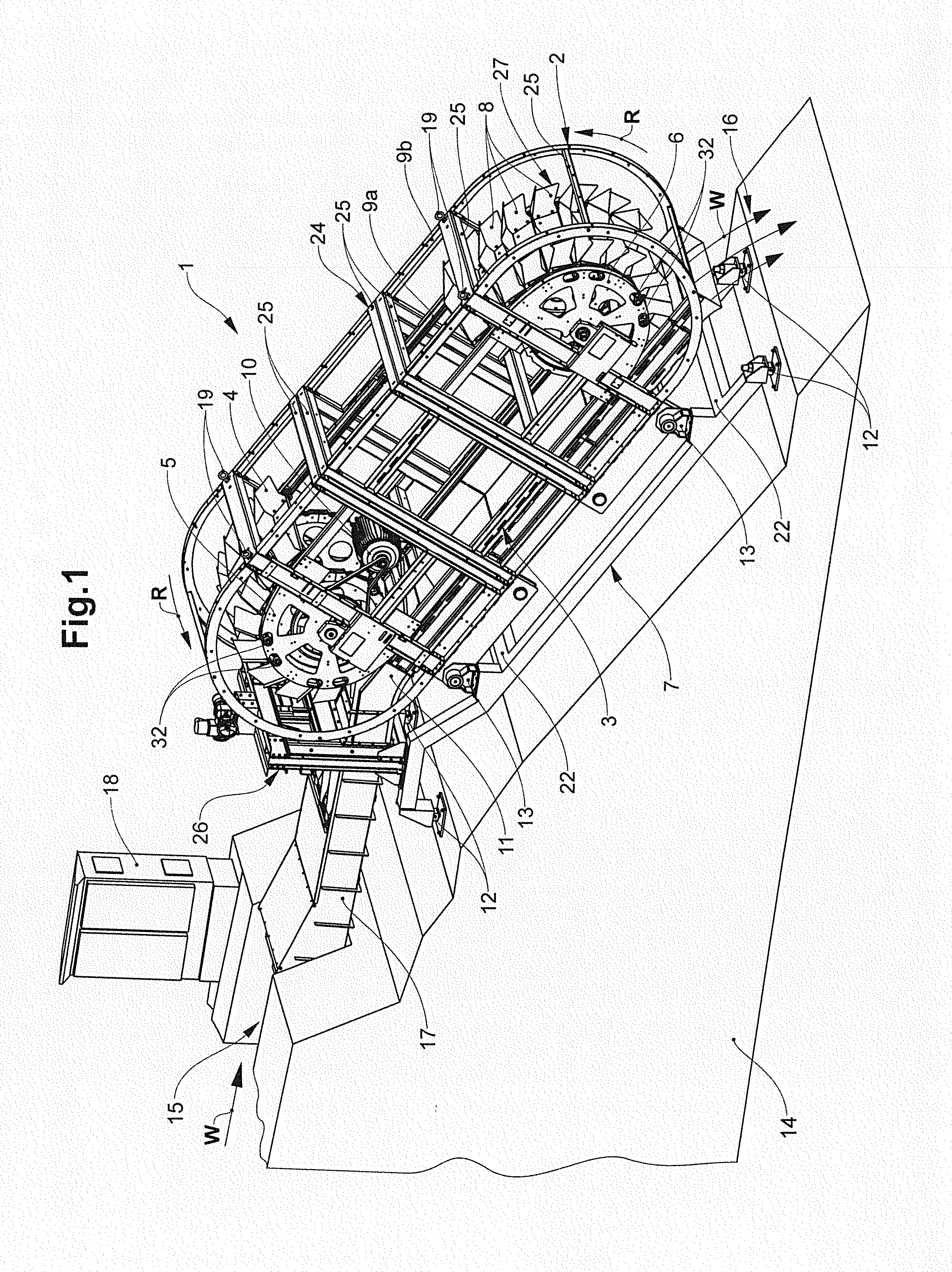
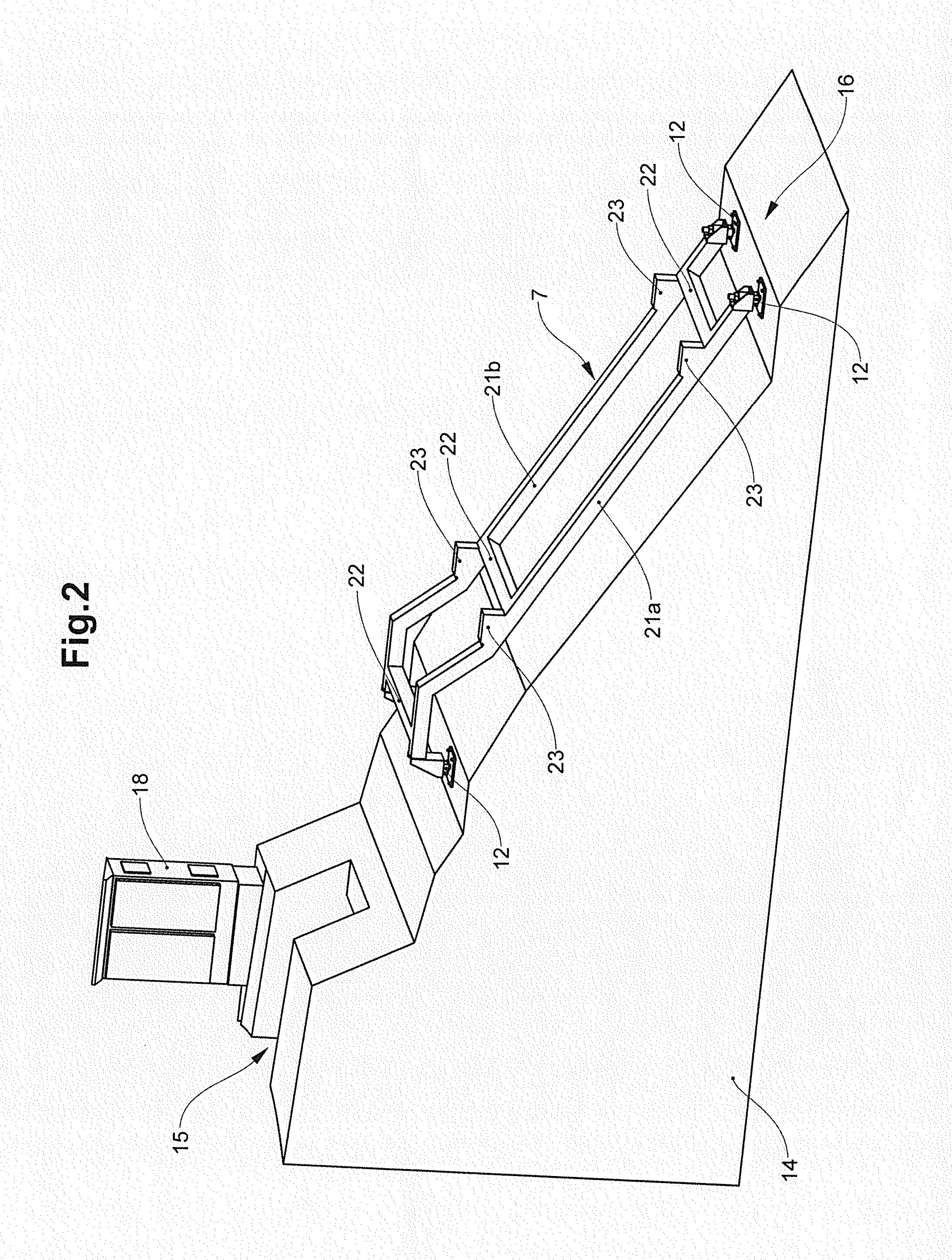
[0128]The plant 1 according to the invention, shown in FIG. 1, for extracting electric energy from water power is installed in a water conveying region with a drop. The plant 1 includes an energy extraction module 2. Process water, in a flow direction W, is fed to the water conveying duct 11 of the energy extraction module 2 from a water inlet region 15 via a water feed duct 17. The process water is guided along the drop through the water conveying duct 11 and in an outlet region 16 is released again from the energy extraction module 2.

[0129]The energy extraction module 2 includes a drive arrangement with a multiplicity of flow-impinged components 8. The flow-impinged components 8 of the drive arrangement are guided or driven in a circulating manner around an upper first deflection element 5 and around a lower second deflection element 6, which is at a distance from the first deflection element 5, in a circulating direction R.

[0130]The flow-impinged components 8 are interconnected, ...


PUM


Abstract

A plant for extracting electric energy from water power. The plant has an energy extraction module designed as an assembly unit, and includes a drive arrangement, with a multiplicity of flow-impinged components, which can be driven in a circulating direction by water power, two spaced-apart deflection elements around which the drive arrangement is guided in a circulating manner, an electric power generator for extracting electric energy from the circulating drive arrangement, a water conveying duct for forming water receiving compartments interacting with the flow-impinged components, and also a module frame, to which are connected the drive arrangement, the deflection elements, the electric power generator and the water conveying duct. The module frame includes an interface via which the energy extraction module is connected to a sub-structure.

Description

BACKGROUND OF THE INVENTION[0001]1. Field of the Invention[0002]The invention relates to a plant for extracting electric energy from water power.[0003]2. Description of Related Art[0004]Knowledge exists of many devices that utilize the potential drop of water or its kinetic energy in order to convert electric energy therefrom. In this context, a differentiation is basically made between two plant types.[0005]According to a first plant type, the kinetic energy of the onflowing water is utilized in order to thereby drive a generator for power generation. To this end, provision is made for flow-impinged components, such as turbine blades, which are impinged upon by a flow of water and set in motion thereby. Water power plants of the first type are found in run-of-the-river power stations or storage power stations. The undershot water wheel is also operated in this way.[0006]According to a second plant type, the kinetic energy of the onflowing water is not primarily used, but rather its...

Claims


Application Information

Patent Timeline
Patent Type & Authority Applications(United States)
IPC IPC(8): F03B13/10F01D15/10F03B17/06F03B11/02F03B7/00
CPCF03B13/10F03B11/02F01D15/10F03B17/061F03B7/00F03B7/006F05B2220/707F05B2230/60F05B2240/91Y02E10/20Y02P70/50
Inventor WIDMER, FELIXRUGE, MARTINFELIX, MARKUS
Owner WRH WALTER REIST HLDG
Why Eureka
Try Eureka