Method and system for secondary air injection coordination with exhaust back pressure valve

a technology of back pressure valve and secondary air injection, which is applied in the direction of mechanical equipment, machines/engines, electric control, etc., can solve the problems of high levels of spark retardation, low vehicle exhaust quality, and increased particulate emissions, so as to achieve the effect of low vehicle exhaust quality

Active Publication Date: 2020-03-03
FORD GLOBAL TECH LLC
View PDF11 Cites 2 Cited by
  • Summary
  • Abstract
  • Description
  • Claims
  • Application Information

AI Technical Summary

Benefits of technology

[0002]Engine cold-start emissions released before an exhaust catalyst has been sufficiently warmed may lower vehicle exhaust quality. Accordingly, engine control systems may use various approaches to expedite attainment of an activation temperature (e.g., a light-off temperature) at the exhaust catalyst.
[0003]One example approach involves increasing exhaust gas temperatures by operating the engine rich to generate high levels of engine-out carbon monoxide (CO), hydrogen (H2), and hydrocarbons and at the same time pumping air (herein referred to as secondary air injection) into the exhaust manifold upstream of the exhaust catalyst. The air pumped into the exhaust manifold may react with the exhaust gases generating an exothermic reaction. As a result, rapid catalyst heating may be achieved. However, the inventors herein have recognized potential issues with such an approach. During secondary air injection, high levels of enrichment are required to increase the percentage of combustible gases in the exhaust, which reduces engine efficiency and increases particulate emissions. Further, high levels of spark retard are required to increase the temperature of the exhaust. As a result, combustion stability and / or engine efficiency may be degraded.
[0005]As an example, during an engine cold start, while an engine temperature is below a threshold temperature, an exhaust back pressure valve coupled downstream of an exhaust catalyst may be adjusted to increase an exhaust back pressure upstream of the valve. At the same time, a secondary air pump may be operated to deliver secondary air into the exhaust manifold upstream of the catalyst. By using a post-catalyst exhaust back pressure valve, the time and temperature that a given mass of exhaust gas is in contact with catalyst parts are substantially increased, expediting catalyst activation. By utilizing secondary air injection in coordination with the exhaust back pressure, a more rapid heating of the exhaust catalyst may be achieved. Further, an amount of enrichment and an amount of spark retard that would be required when exhaust back pressure increase and secondary air injection are utilized coordinately for catalyst warm-up may be less than the fuel injection amount and the spark retard that would be required during secondary air injection alone. Consequently, by using less spark retard, efficiency and combustion stability may be improved, and by using less enrichment, particulate emissions and efficiency may be improved.
[0006]In this way, exhaust back pressure and secondary air injection can be advantageously used to expedite exhaust catalyst activation. The combination enables exhaust catalyst activation to be expedited without compromising combustion stability and efficiency. By rapidly heating the exhaust catalyst, cold-start exhaust emissions may be reduced.

Problems solved by technology

Engine cold-start emissions released before an exhaust catalyst has been sufficiently warmed may lower vehicle exhaust quality.
However, the inventors herein have recognized potential issues with such an approach.
During secondary air injection, high levels of enrichment are required to increase the percentage of combustible gases in the exhaust, which reduces engine efficiency and increases particulate emissions.
Further, high levels of spark retard are required to increase the temperature of the exhaust.
As a result, combustion stability and / or engine efficiency may be degraded.

Method used


Image

  • Method and system for secondary air injection coordination with exhaust back pressure valve
  • Method and system for secondary air injection coordination with exhaust back pressure valve
  • Method and system for secondary air injection coordination with exhaust back pressure valve

Examples


Embodiment Construction

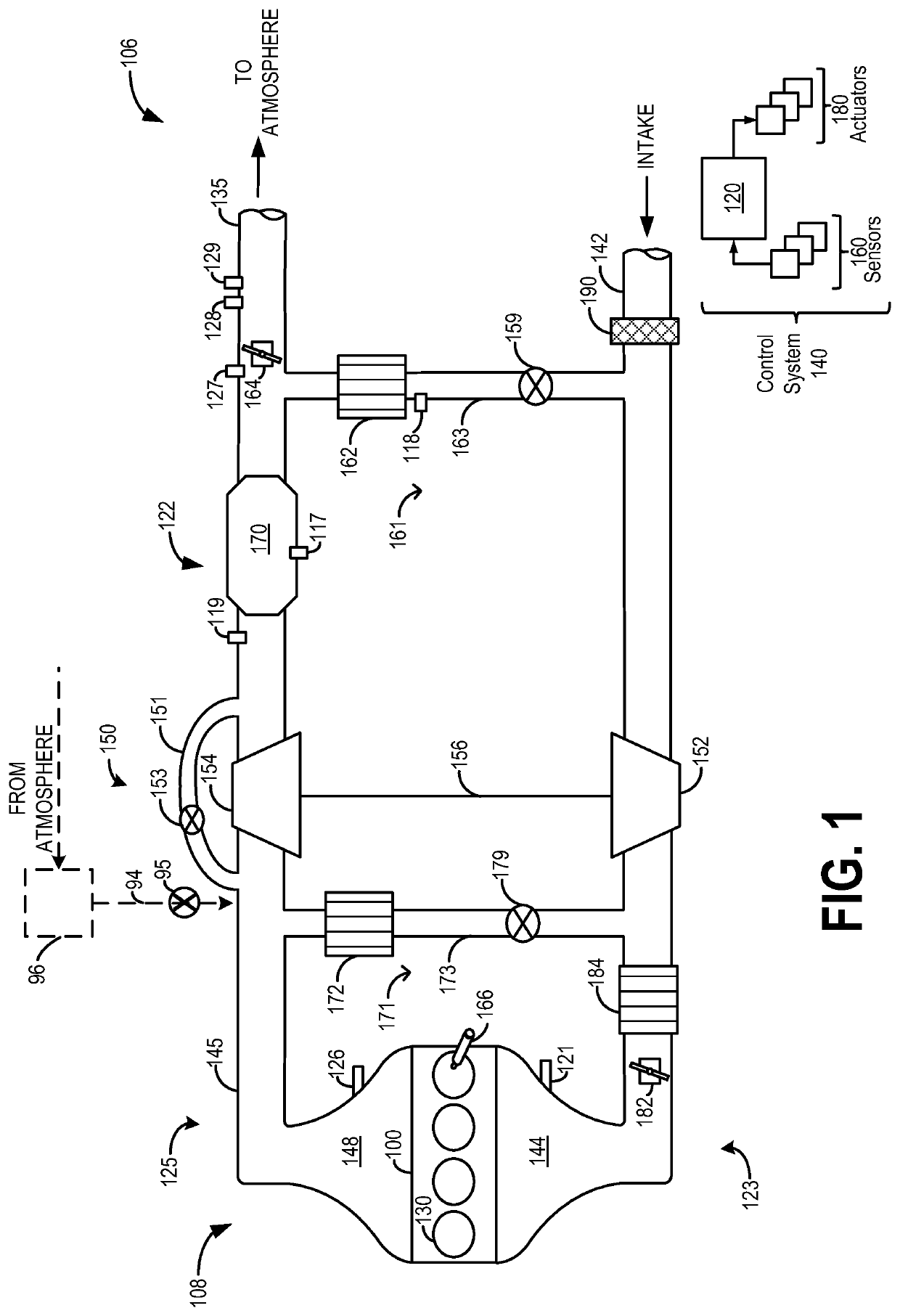
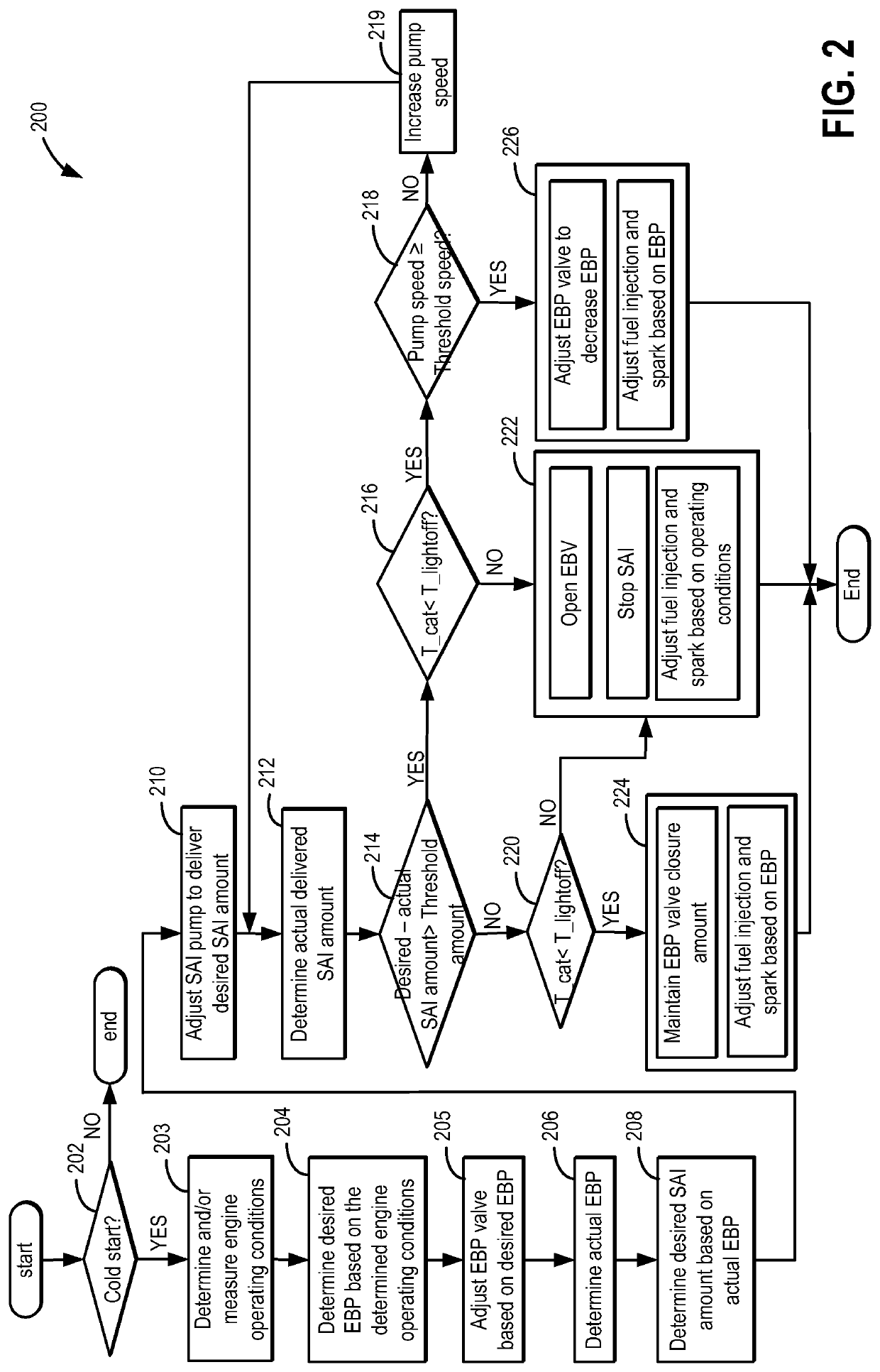
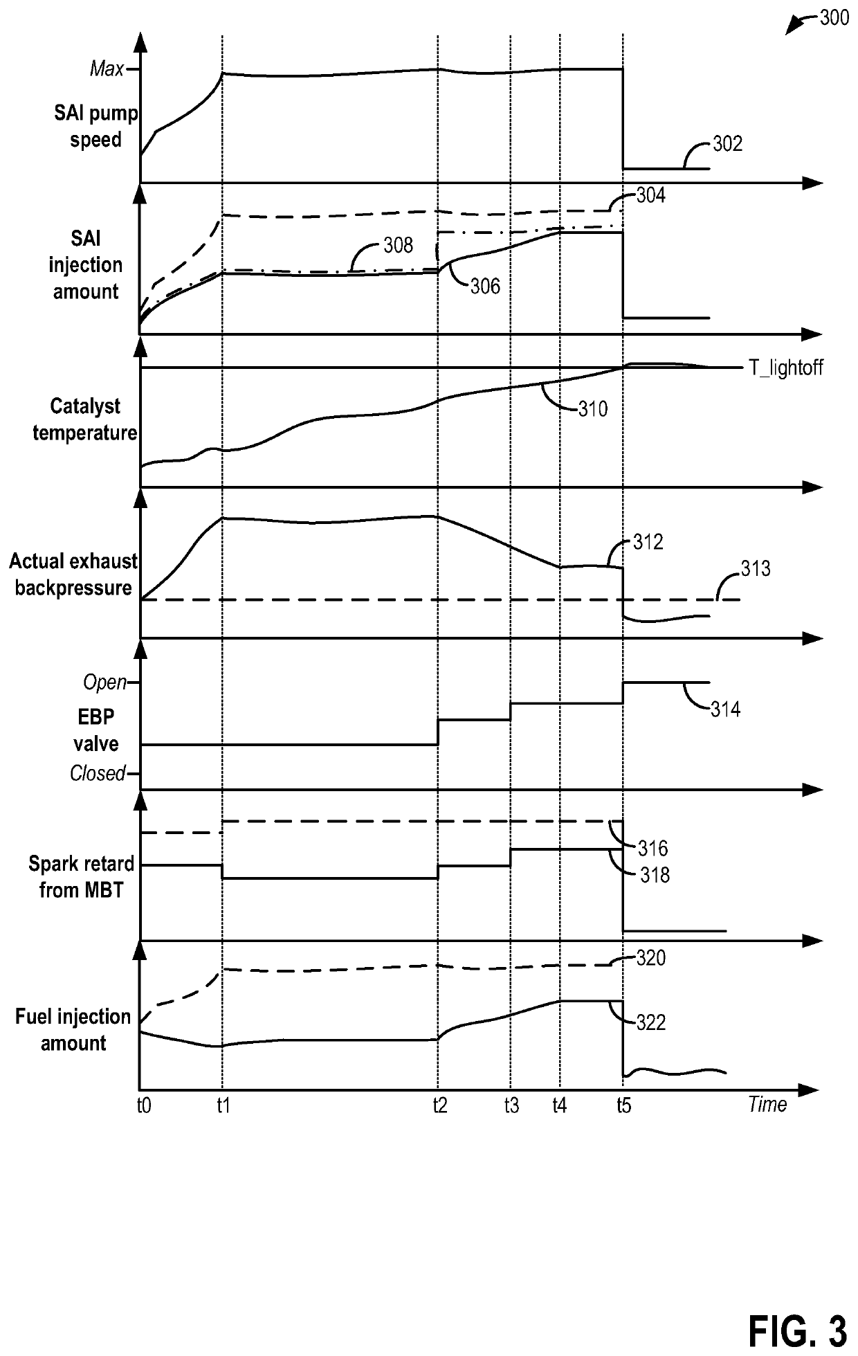
[0011]Methods and systems are provided for expediting engine warm-up and catalyst activation in a vehicle engine, such as the engine system of FIG. 1. During an engine cold-start, exhaust backpressure and secondary air injection may be advantageously used to quickly raise a temperature of an exhaust catalyst. A controller may be configured to perform a control routine, such as the example routine of FIG. 2, to adjust an exhaust valve positioned downstream of an exhaust catalyst to raise an exhaust backpressure while delivering secondary air. By coordinately utilizing exhaust back pressure increase with secondary air injection, an amount of enrichment and spark retard required may be reduced. As a result, combustion stability, efficiency, and particulate emissions may be improved while achieving rapid catalyst heating. Example back pressure valve and secondary air injection amount adjustments are described at FIG. 3.

[0012]FIG. 1 shows a schematic depiction of a vehicle system 106. Th...


PUM


Abstract

Methods and systems are provided for controlling and coordinating control of a post-catalyst exhaust back pressure valve and secondary air injection to expedite catalyst heating. By adjusting the exhaust back pressure valve to increase the exhaust backpressure and injecting secondary air into an exhaust passage upstream of the catalyst during cold start conditions, exhaust catalyst activation may be expedited.

Description

FIELD[0001]The present description relates to systems and methods for expediting heating of an exhaust catalyst utilizing secondary air injection in coordination with exhaust back pressure valve adjustment, in particular, during an engine cold start.BACKGROUND AND SUMMARY[0002]Engine cold-start emissions released before an exhaust catalyst has been sufficiently warmed may lower vehicle exhaust quality. Accordingly, engine control systems may use various approaches to expedite attainment of an activation temperature (e.g., a light-off temperature) at the exhaust catalyst.[0003]One example approach involves increasing exhaust gas temperatures by operating the engine rich to generate high levels of engine-out carbon monoxide (CO), hydrogen (H2), and hydrocarbons and at the same time pumping air (herein referred to as secondary air injection) into the exhaust manifold upstream of the exhaust catalyst. The air pumped into the exhaust manifold may react with the exhaust gases generating a...

Claims


Application Information

Patent Timeline
Patent Type & Authority Patents(United States)
IPC IPC(8): F02D41/02F01N3/20
CPCF02D41/025F01N3/2006F02D41/0255F02D41/064F02D41/1448F02D2200/0802F02D2250/34F02D9/04F02M26/05F02M26/06F02M26/24F02M26/47Y02T10/12
Inventor LEONE, THOMAS G.
Owner FORD GLOBAL TECH LLC
Why Eureka
Try Eureka