Systems and methods for monitoring building health

a technology for building health and monitoring systems, applied in the field of maintenance of buildings, can solve problems such as recurring water leakage in the attic or upper level(s) of the building, deterioration of buildings, and failure of components

Active Publication Date: 2020-03-03
STATE FARM MUTAL AUTOMOBILE INSURANCE COMPANY
View PDF43 Cites 49 Cited by
  • Summary
  • Abstract
  • Description
  • Claims
  • Application Information

AI Technical Summary

Problems solved by technology

The effects of environmental conditions such as wind, heat and cold, solar rays, shifting earth, pests, and various forms of precipitation such as rain, sleet, snow, hail, and humidity all contribute to the deterioration of buildings over time.
However, over the course of the component's installed life, exposure to various environmental conditions can cause the component to deteriorate and begin to fail.
However, a hail storm event, for example, may cause some shingles to break or otherwise compromise the integrity of the roofing system, leading to recurring water leaks in the attic or upper level(s) of the building.
In many cases, these leaks may not be immediately evident, as some homeowners may not frequent their attics, or may not otherwise regularly inspect their home's systems.
As such, these system integrity failures may go undetected for weeks, months, or years until evidence presents itself more apparently to the homeowner.
This delay in promptly detecting such building system failures may lead to additional damage to the building.
This additional or ancillary damage created by the undetected compromise may cause building owners to have to spend significantly more to repair the building, as they pay to fix not only the underlying system failure (e.g., the leaky roof) but also the damage caused by not promptly detecting the failure (e.g., the mold growth in an attic and the staining on the interior ceiling).

Method used


Image

  • Systems and methods for monitoring building health
  • Systems and methods for monitoring building health
  • Systems and methods for monitoring building health

Examples


Embodiment Construction

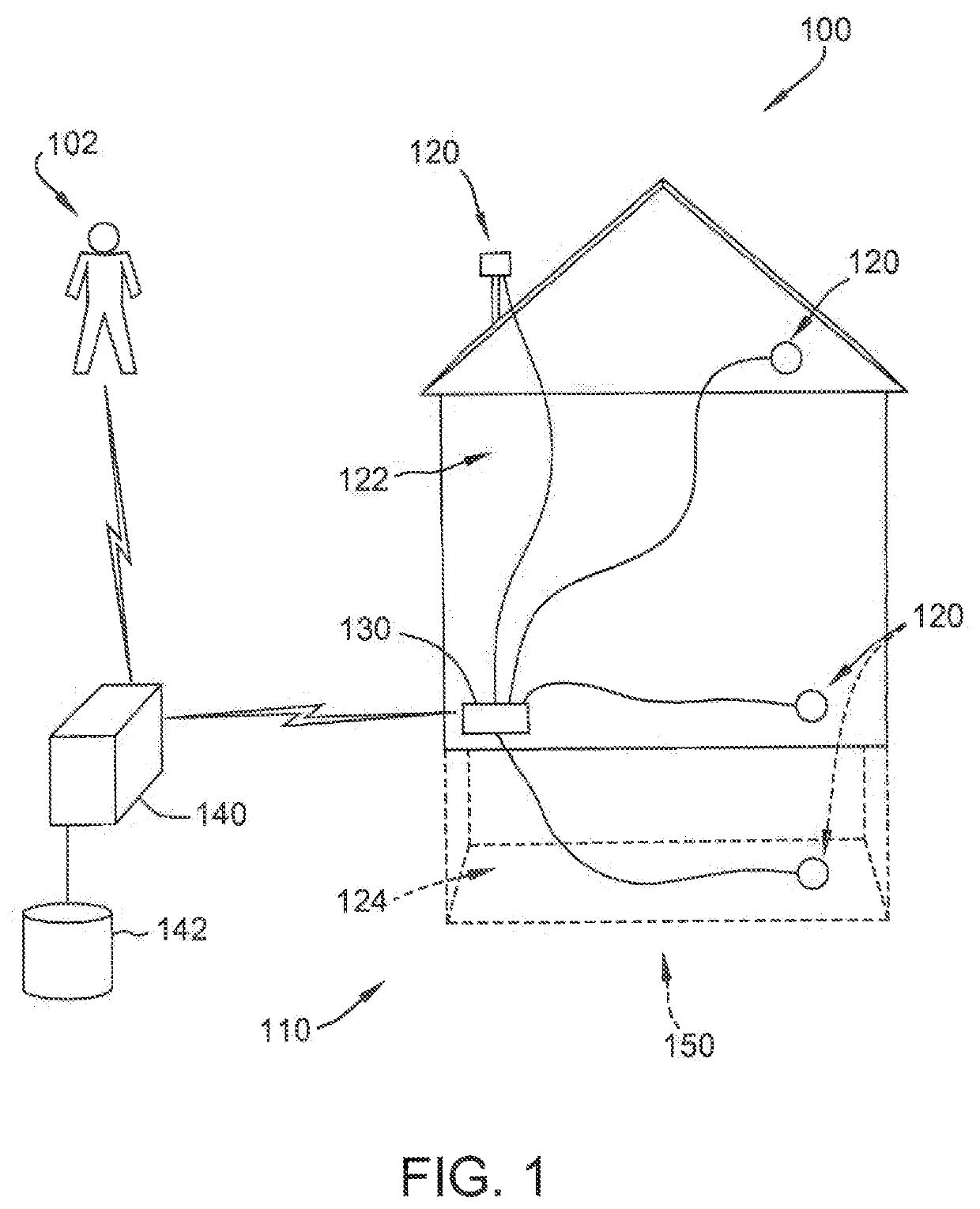
[0033]A system and method may include and / or employ an Ultra-Smart Home (e.g., a home with sensors embedded in construction or building materials throughout a home or building, or embedded in building materials in select areas of the home or building) in wired or wireless communication with a Home-Health Data Recorder (or smart home controller). Similar to a flight data recorder that monitors aircraft and pilot activities, the home data recorder (or “black box”) may log and alert a homeowner of potential defects that may impact the integrity and longevity of the property.

[0034]For example, the monitoring system may be in wireless communication or data transmission with construction / material sensors strategically placed throughout the home (in foundation, attic, basement, roof, etc.). In one embodiment, the sensors may detect or discover a vapor barrier breach that may be allowing moisture to penetrate the construction material that, in turn, results in mold and, ultimately, the dest...


PUM


Abstract

A building monitoring computer system for monitoring building integrity may be provided. Various types of sensors may be embedded throughout or within certain portions of different types of building or construction material making up the building, such as within roofing, foundation, or structural materials. The sensors may be in wireless communication with a home controller. The sensors may be water, moisture, temperature, vibration, or other types of sensors, and may detect unexpected or abnormal conditions within the home. The sensors and / or home controller may transmit alerts to a mobile device of the home owner associated with the unexpected condition, and / or that remedial actions may be required to repair the home or mitigate further damage to the home. The sensor data may also be communicated to an insurance provider remote server to facilitate the insurance provider communicating insurance-related recommendations, updating insurance policies, or preparing insurance claims for review for home owners.

Description

CROSS-REFERENCE TO RELATED APPLICATIONS[0001]This application is a continuation of, and claims the benefit of, U.S. patent application Ser. No. 15 / 017,374, entitled “Systems and Methods for Monitoring Building Health” and filed Feb. 5, 2016, which claims the benefit of priority of U.S. Provisional Patent Application Ser. No. 62 / 118,359, filed Feb. 19, 2015, and of U.S. Provisional Patent Application Ser. No. 62 / 203,743, filed Aug. 11, 2015, the contents of all of which are hereby incorporated by reference, in their entireties and for all purposes, herein.FIELD OF THE DISCLOSURE[0002]The present disclosure relates to maintaining a building and, more particularly, to systems and methods for monitoring the health of a building, such as a residential house.BACKGROUND[0003]Commercial and residential buildings are exposed to the elements during the course of their use. The effects of environmental conditions such as wind, heat and cold, solar rays, shifting earth, pests, and various forms...

Claims


Application Information

Patent Timeline
Patent Type & Authority Patents(United States)
IPC IPC(8): G06Q40/08E04B1/70E04B1/72E04B1/92E04B1/64G05B15/02E04B1/98G06N5/04
CPCE04B1/64E04B1/92G06N5/04E04B1/72G06Q40/08E04B1/98E04B1/70G05B15/02E02D27/04E04B1/0007E04B1/665E04B1/74E04D13/006G08B21/20E04B2002/565G01M3/16G01M3/24G01M5/0066H04L12/2818
Inventor JACOB, MICHAEL S.
Owner STATE FARM MUTAL AUTOMOBILE INSURANCE COMPANY
Why Eureka
Try Eureka