
Fluid pump with rotating pumping element wear reduction

a technology of rotating pumping element and fluid pump, which is applied in the direction of liquid fuel engine, fuel injecting pump, fuel injection apparatus, etc., can solve the problems of low flow output of fuel pump, wear of surfaces, and insufficient fineness to strain out all harmful contaminants, so as to reduce or eliminate contamination, prolong the service life of fluid pump, and minimize wear

Active Publication Date: 2020-03-10
DELPHI TECH IP LTD
View PDF11 Cites 0 Cited by
  • Summary
  • Abstract
  • Description
  • Claims
  • Application Information

AI Technical Summary

Benefits of technology

[0004]Briefly described, a fluid pump includes a housing; an inlet plate disposed within the housing, the inlet plate having an inlet which introduces fluid to the housing; an outlet plate disposed within the housing, the outlet plate having an outlet plate outlet passage; an electric motor having a shaft which rotates about an axis; an outlet which discharges fluid from the housing; a pumping element rotationally coupled to the shaft such that rotation of the pumping element by the shaft causes fluid to be pumped from the inlet to the outlet plate outlet passage and through the outlet, the pumping element being located axially between the inlet plate and the outlet plate such that the inlet plate interfaces with the pumping element in an inlet sealing surface interface and such that the outlet plate interfaces with the pumping element in an outlet sealing surface interface; a purge passage downstream of the outlet plate outlet passage which receives fluid from the outlet plate outlet passage, the purge passage being in fluid communication with the inlet sealing surface interface and with the outlet sealing surface interface; and a filter downstream of the outlet plate outlet passage which filters fluid that passes through the purge passage prior to reaching the inlet sealing surface interface and the outlet sealing surface interface. The purge passage and the filter minimize or eliminate contamination at the inlet sealing surface interface and the outlet sealing surface interface, thereby minimizing wear and extending the service life of the fluid pump.

Problems solved by technology

If the axial clearances are excessive, leakage may occur, which results in low flow output of the fuel pump.
Consequently, the pre-filter is normally constrained by cavitation considerations in gasoline arrangements or by fuel waxing considerations in diesel fuel arrangements and therefore is not fine enough to strain out all harmful contaminants.
Rotation of the pumping element, together with the presence of contaminants in the axial clearances, results in abrasion which results in wear of the surfaces of the pumping element, inlet plate, and outlet plate, thereby decreasing the flow output of the fuel pump over time due to ever-increasing axial clearances.

Method used


Image

  • Fluid pump with rotating pumping element wear reduction
  • Fluid pump with rotating pumping element wear reduction
  • Fluid pump with rotating pumping element wear reduction

Examples


Embodiment Construction

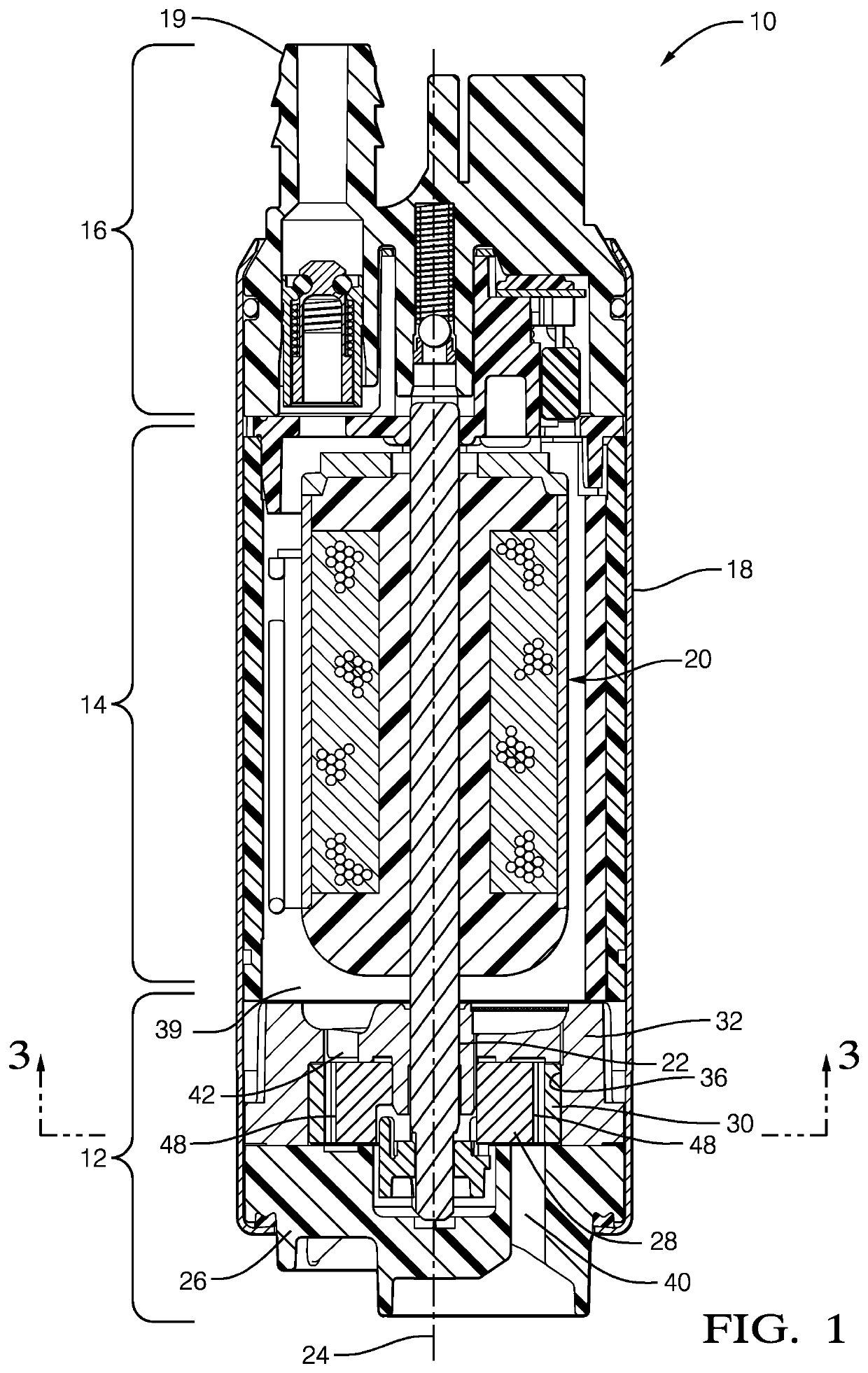
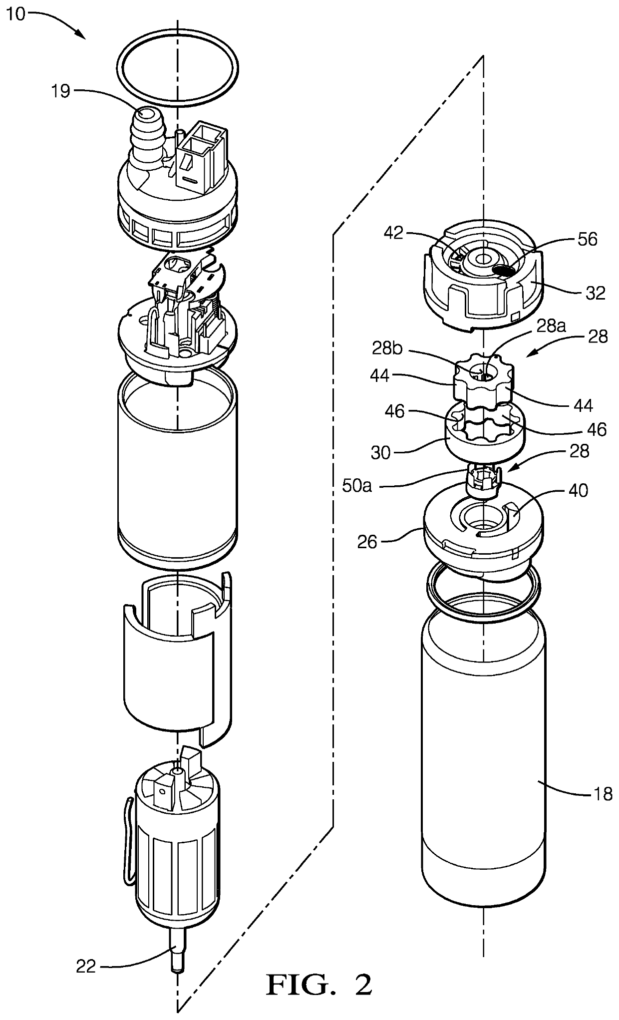
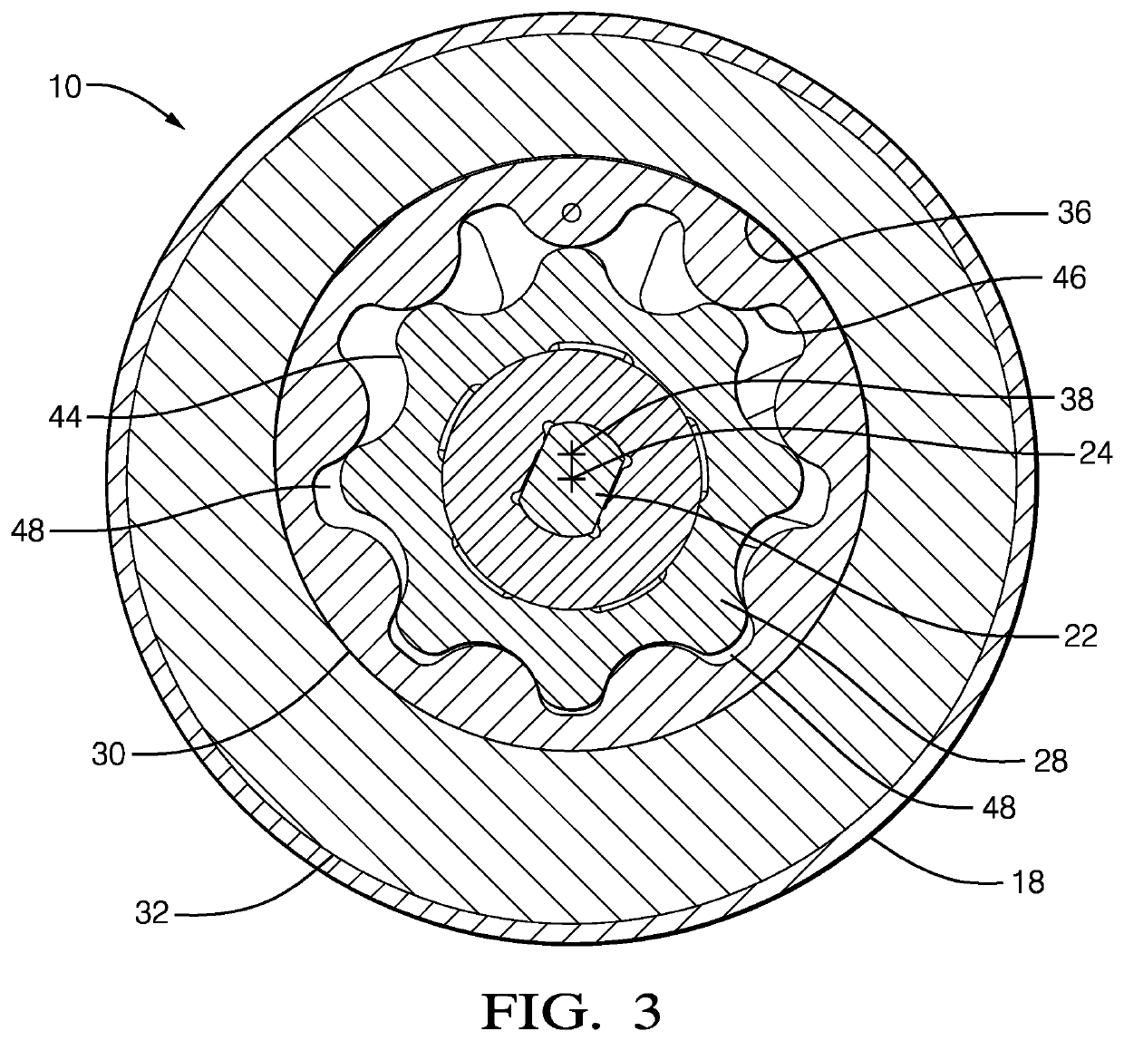
[0010]Reference will first be made to FIGS. 1 and 2 which are an axial cross-sectional view and an exploded isometric view respectively of a fluid pump illustrated as a fuel pump 10 for pumping liquid fuel, by way of non-limiting example only gasoline or diesel fuel, from a fuel tank (not shown) to an internal combustion engine (not shown). While the fluid pump is illustrated as fuel pump 10, it should be understood that the invention is not to be limited to a fuel pump, but could also be applied to fluid pumps for pumping fluids other than fuel. Fuel pump 10 generally includes a pump section 12 at one end, a motor section 14 adjacent to pump section 12, and an outlet section 16 adjacent to motor section 14 at the end of fuel pump 10 opposite pump section 12. A housing 18 of fuel pump 10 retains pump section 12, motor section 14 and outlet section 16 together. Fuel enters fuel pump 10 at pump section 12, a portion of which is rotated by motor section 14 as will be described in more ...


PUM


Abstract

A fluid pump includes an inlet plate with an inlet; an outlet plate, the outlet plate having an outlet plate outlet passage; an outlet; an electric motor having a shaft which rotates; a pumping element coupled to the shaft such that rotation of the pumping element by the shaft causes fluid to be pumped from the inlet to the outlet, the inlet plate interfacing with the pumping element in an inlet sealing surface interface and the outlet plate interfacing with the pumping element in an outlet sealing surface interface; a purge passage which receives fluid from the outlet plate outlet passage, the purge passage being in fluid communication with the inlet sealing surface interface and the outlet sealing surface interface; and a filter downstream of the outlet plate outlet passage which filters fluid that passes through the purge passage prior to reaching the inlet and outlet sealing surface interfaces.

Description

TECHNICAL FIELD OF INVENTION[0001]The present invention relates to a fluid pump which pumps fluid; more particularly to a fluid pump with a rotating pumping element disposed axially between two plates, and still even more particularly to such a fluid pump which includes a purge passage and filter to minimize or eliminate contamination which can infiltrate into the axial clearances between the pumping element and plates.BACKGROUND OF INVENTION[0002]Fluid pumps, and more particularly fuel pumps for pumping fuel, for example, from a fuel tank of a motor vehicle to an internal combustion engine of the motor vehicle, are known. A typical fuel pump includes a housing within which generally includes a pump section, a motor section, and an outlet section. The pump section includes a rotating pumping element, either positive displacement or centrifugal, located axially between an inlet plate and an outlet plate. The pumping element imparts energy into the fuel while forcing the fuel to move ...

Claims


Application Information

Patent Timeline
Patent Type & Authority Patents(United States)
IPC IPC(8): F04C13/00F04C2/10F04C2/08F04C11/00F04C15/06F04C15/00F02M59/12
CPCF04C2/10F04C15/0003F04C15/008F04C13/007F04C13/005F04C2/102F04C11/008F02M59/12F04C2/08F04C15/06F04C2210/1044F04C2240/40F04C2240/30
Inventor FISCHER, JOHN G.
Owner DELPHI TECH IP LTD
Learn More