Bone fusion device

a bone fusion and bone technology, applied in the direction of osteosynthesis devices, bone plates, fasteners, etc., can solve the problems of affecting the stability of the patient, and requiring reoperation, so as to prevent other tissues from being damaged by the screw effect of safe bone fusion surgery

Active Publication Date: 2020-03-17
L&K BIOMED CO LTD
View PDF12 Cites 8 Cited by
  • Summary
  • Abstract
  • Description
  • Claims
  • Application Information

AI Technical Summary

Benefits of technology

[0021]According to the present invention, it is possible to safely perform the bone fusion surgery by pulling the distant bone body in a surgery direction toward the adjacent bone body in the surgery direction while fusing the adjacent bone bodies. In particular, it is possible to prevent other tissues from being damaged by the screw while performing the bone fusion surgery.
[0022]In addition, an operator may adjust an amount of pulling of the screw as necessary while performing the bone fusion surgery.

Problems solved by technology

Conventional lumbar fusion surgery may result in excessive displacement at adjacent segments other than a surgical site after the operation, resulting in secondary lesions at the adjacent segments during a long-term use and reoperation is often required.
This syndrome is accompanied by lumbar pain, leading to pain in the thighs and below the hips, and sometimes pain along a sciatic nerve occurs.
Further, in a severe case, it has been reported that it becomes difficult to sit.
However, since the sacrum and the ilium are simply fixed using a screw during the operation, loosening occurs at the joint site after a long period of time, and therefore, there is a problem that the reoperation should be performed.
However, if rotating the screw until it comes into contact with the washer, the screw may penetrate the bone body located at a region far from the washer of the bone body to be fused, thereby damaging other tissues of a human body.
In addition, if tightening the screw only to a position in which the screw does not penetrate the bone body located at the region far from the washer by using an observation equipment, the bone bodies to be fused cannot be sufficiently adhered to each other.
Accordingly, screws having a required length should be prepared based on differences in the bone structure of each patient, and thus the efficacy of this treatment may be uncertain.

Method used


Image

  • Bone fusion device
  • Bone fusion device
  • Bone fusion device

Examples


embodiment 1

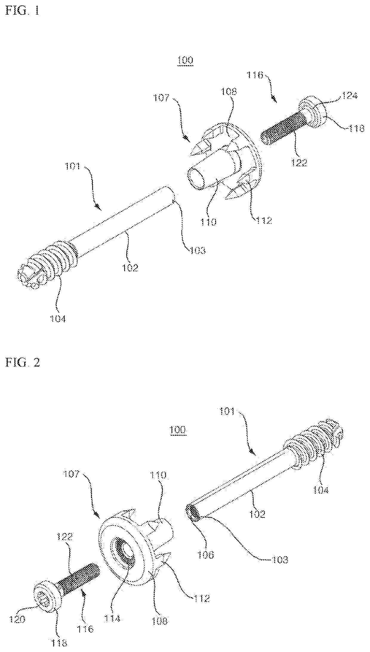
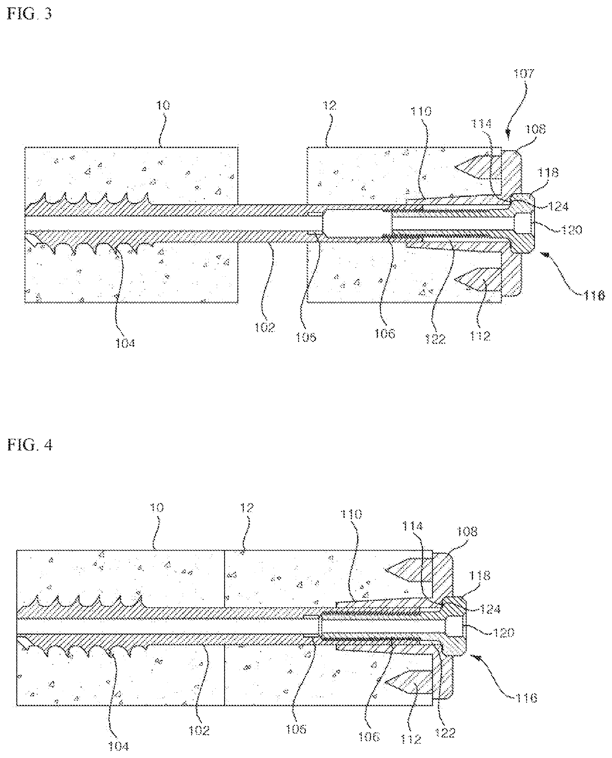
[0036]FIGS. 1 and 2 illustrate a bone fusion device 100 of the present invention. The bone fusion device 100 generally includes a bone screw 101 inserted into bone bodies, a washer 107 into which the bone screw 101 is inserted and supported by the bone body, and an adjustment screw 116 screwed with the bone screw 101 to adjust an interval between the washer 107 and the bone screw 101. The bone fusion device 100 may be made of metal or an alloy, and for example, titanium, which is harmless to the human body, may be used.

[0037]The bone screw 101 includes a shank 102 having an elongated shape with a circular cross-section, a screw thread 104 formed on one end portion of the shank 102, and an adjustment female thread 106 formed in the other end portion of the shank 102.

[0038]The shank 102 with a smooth surface has a structure for facilitating an insertion thereof into the washer 107, as well as preventing an interference with the bone body, when the bone screw 101 is pulled toward the ...

embodiment 4

[0070]Next, a bone fusion device 200 of the present invention will be described with reference to FIGS. 9 to 12. The bone fusion device 200 generally includes a bone screw 201 inserted into bone bodies, a washer 207 inserted into the bone screw 201 and supported by the bone body, and an adjustment screw 216 screwed with the bone screw 201 to adjust an interval between the washer 207 and the bone screw 201. The bone fusion device 200 may be made of metal or an alloy, and for example, titanium, which is harmless to the human body, may be used.

[0071]The bone screw 201 includes a shank 202 having an elongated shape with a circular cross-section, a screw thread 204 formed on one end portion of the shank 202, and an adjustment female thread 206 formed in the other end portion of the shank 202.

[0072]The shank 202 with a smooth surface has a structure for facilitating an insertion thereof into the washer 207, as well as preventing an interference with the bone body, when the bone screw 201...

embodiment 5

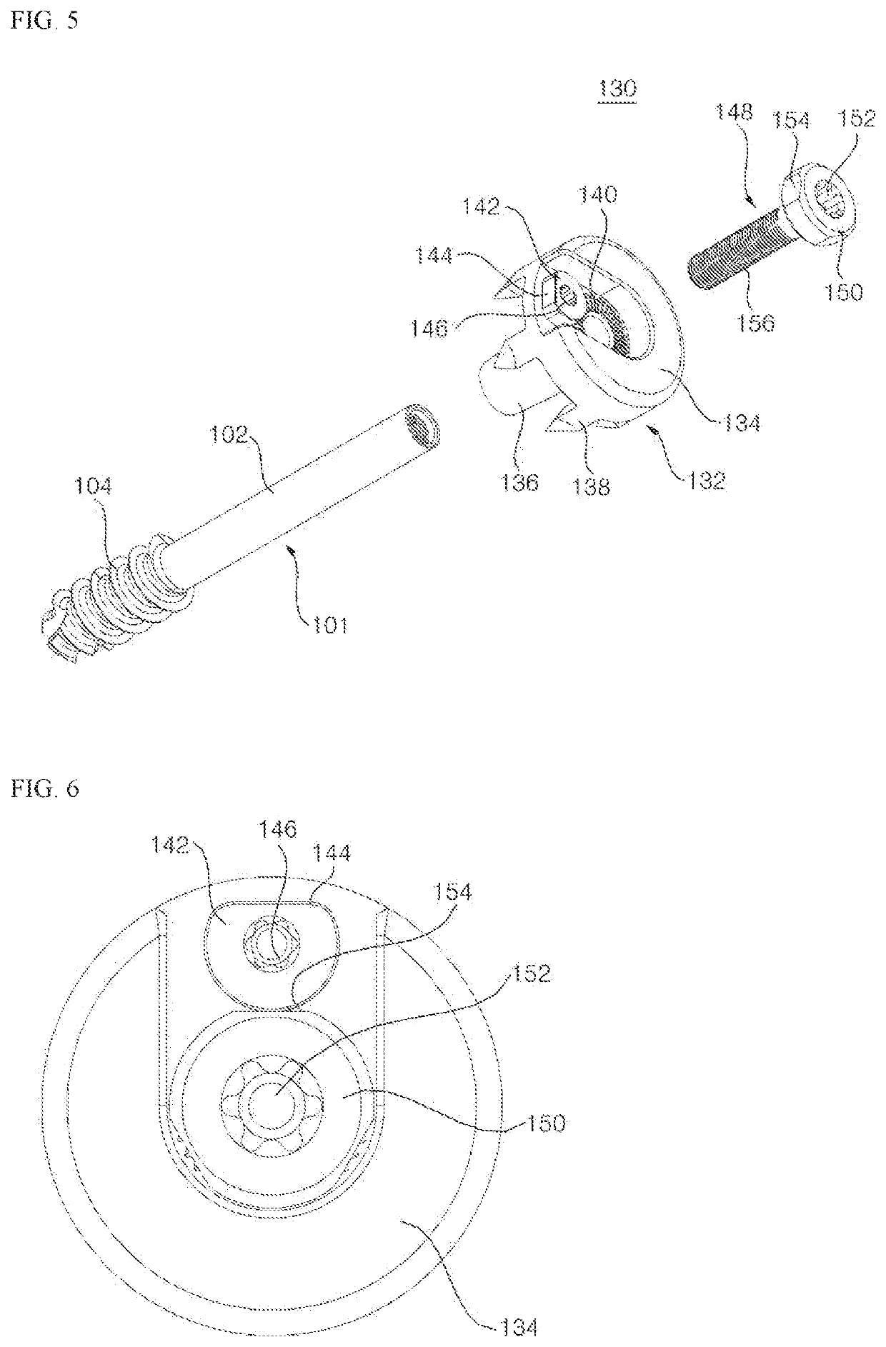
[0082]Next, a bone fusion device 230 of the present invention will be described with reference to FIGS. 13 and 14. The bone fusion device 230 generally includes a bone screw 201 inserted into bone bodies, a washer 232 into which the bone screw 201 is inserted and supported by the bone body, and an adjustment screw 216 screwed with the bone screw 201 to adjust an interval between the washer 232 and the bone screw 201. The bone fusion device 200 may be made of metal or an alloy, and for example, titanium, which is harmless to the human body, may be used.

[0083]The bone screw 201 and the adjustment screw 216 have same configuration as those of Embodiment 4, therefore will not be described in detail.

[0084]The washer 232 includes a through hole into which the other end portion of the shank 202 is inserted and should have a cross-sectional area larger than that of the bone screw so as to be supported by the bone bodies. For this purpose, the washer 232 includes a washer tube 210 having a ...


PUM


Abstract

The present invention provides a bone fusion device which allows a distant bone body in a surgery direction to be pulled toward an adjacent bone body in the surgery direction while fusing the adjacent bone bodies. The bone fusion device includes a bone screw which includes a shank having an elongated shape with a circular cross-section, a screw thread formed on one end portion of the shank, and an adjustment female thread formed in the other end portion of the shank; a washer which includes a through hole into which the other end portion of the shank is inserted, and has a cross-sectional area larger than that of the bone screw; and an adjustment screw having an adjustment male thread screwed with the adjustment female thread of the bone screw through a through hole of the washer.

Description

CROSS-REFERENCE TO RELATED APPLICATIONS[0001]This application claims priority to Korean Patent Application No. 10-2015-0015161 filed on Jan. 30, 2015 in the Korean Intellectual Property Office, and International Application No. PCT / KR2016 / 000885, filed on Jan. 27, 2016, the entire disclosures of which are incorporated herein by reference.FIELD OF THE INVENTION[0002]The present invention relates to a bone fusion device, and more specifically, to a bone fusion device which allows a distant bone body in a surgery direction to be pulled toward an adjacent bone body in the surgery direction while fusing the adjacent bone bodies.BACKGROUND OF THE INVENTION[0003]Conventional lumbar fusion surgery may result in excessive displacement at adjacent segments other than a surgical site after the operation, resulting in secondary lesions at the adjacent segments during a long-term use and reoperation is often required. In particular, when a problem occurs in a joint between a sacrum (sacral verte...

Claims


Application Information

Patent Timeline
Patent Type & Authority Patents(United States)
IPC IPC(8): A61B17/86A61B17/70A61B17/80
CPCA61B17/8042A61B17/8047A61B17/8685A61B17/809A61B17/8605A61B17/8695A61B17/863A61B17/7055A61B2017/8655
Inventor KANG, GOOK-JINKIM, SUNNY
Owner L&K BIOMED CO LTD
Why Eureka
Try Eureka