Hydraulic system

a technology of hydraulic system and electromagnetic proportional valve, which is applied in the direction of servomotors, hoisting equipment, transportation and packaging, etc., can solve the problem that the controller cannot control the electromagnetic proportional valve, and achieve the effect of safe operation

Active Publication Date: 2019-03-21
TADANO LTD
View PDF2 Cites 2 Cited by
  • Summary
  • Abstract
  • Description
  • Claims
  • Application Information

AI Technical Summary

Benefits of technology

[0018]With the hydraulic system according to the present invention, an operator can safely perform work d

Problems solved by technology

In the electric operation system, when an electric circuit portion has f

Method used


Image

  • Hydraulic system
  • Hydraulic system
  • Hydraulic system

Examples


Embodiment Construction

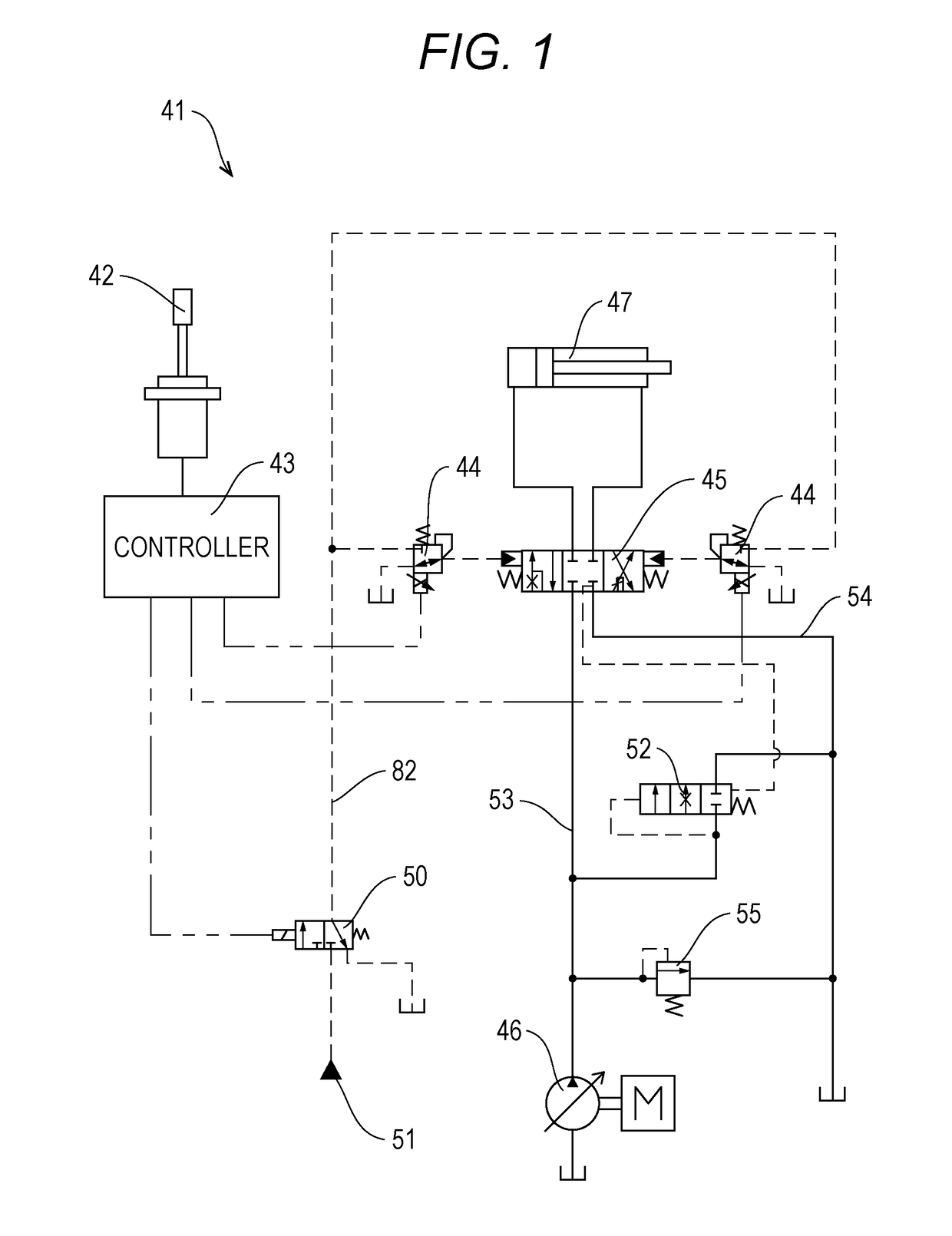
[0025]FIG. 1 is a diagram illustrating a hydraulic circuit in a normal state of a hydraulic system 41 according to an embodiment of the present invention.

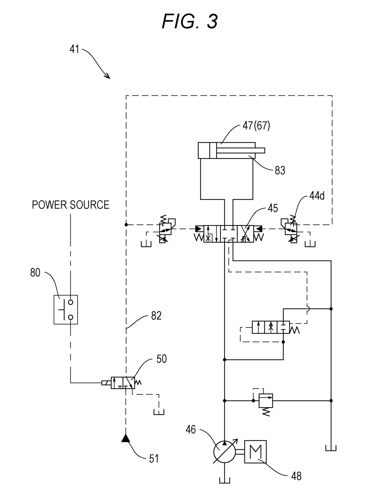
[0026]The hydraulic system 41 includes a main circuit for supplying an operating pressure to an actuator 47 and a pilot circuit for operating the main circuit. The main circuit includes a hydraulic pump 46, a motor 48, a control valve 45, a pressure-compensated flow regulating valve 52, and a relief valve 55. The pilot circuit includes an operation lever 42, a controller 43, an electromagnetic proportional valve 44, a pilot pressure unloading solenoid valve 50, and an emergency operation activation switch 80 (see FIGS. 3 and 5). That is, an electric operation system is applied to the pilot circuit.

[0027]In the hydraulic system 41, the pilot circuit constitutes a pilot pressure supply unit for supplying a pilot pressure to the control valve 45. The pilot pressure unloading solenoid valve 50 and the emergency operation activation swi...


PUM


Abstract

This hydraulic system is provided with a hydraulic pump, a control valve, and a pilot pressure supply unit. The pilot pressure supply unit has: an electromagnetic proportional valve that has a detent-type emergency manual operation function with which a pilot oil passage can be opened manually and generates pilot pressure for a control valve; a controller that controls the degree of opening of the electromagnetic proportional valve in accordance with the operation of an operation lever; and a pilot pressure switching unit that switches the oil pressure state of the pilot pressure supply unit between an on-loading state and an unloading state. The pilot pressure switching unit performs control to implement the unloading state when the electromagnetic proportional valve is being opened manually and performs control to implement the on-loading state after the electromagnetic proportional valve has been opened manually.

Description

TECHNICAL FIELD[0001]The present invention relates to a hydraulic system of a working machine, and particularly to a hydraulic system including an electric operation system for electrically controlling a control valve of the hydraulic system.BACKGROUND ART[0002]In recent years, for an operation system of a hydraulic working machine, an electric operation system for electrically controlling a control valve of a hydraulic system has been used. In the electric operation system, an electric signal from an operation lever is input to a controller, and an electromagnetic proportional valve operates according to the electric signal from the controller. By the operation of the electromagnetic proportional valve, a pilot pressure of the control valve of the hydraulic system is controlled.[0003]The electric operation system can be subjected to advanced control by causing a controller to execute control logic and is becoming an important technique for responding to a high demand such as energy...

Claims


Application Information

Patent Timeline
IPC IPC(8): F15B20/00F15B11/10F15B13/043B66C23/88B66C15/00
CPCF15B20/002F15B11/10F15B13/043B66C23/88B66C15/00F15B2211/7054F15B2211/575F15B2211/528F15B2211/6346B66C23/42B66C23/54B66C13/20
Inventor KAWABUCHI, NAOTOYOSHIDA, NAOFUMIMASUDA, NAOTAKAFUKUMORI, YASUHIRO
Owner TADANO LTD
Why Eureka
Try Eureka