
Laser welded scanner assemblies

a scanner and assembly technology, applied in the field of scanning assemblies, can solve the problems of limiting the size and performance of current laser scanning devices, scanner assemblies with sufficient yield and sufficiently low cost, and especially problematic, so as to facilitate the improvement of yield, reduce costs, and increase performance

Active Publication Date: 2020-03-17
MICROVISION
View PDF15 Cites 14 Cited by
  • Summary
  • Abstract
  • Description
  • Claims
  • Application Information

AI Technical Summary

Benefits of technology

The patent describes a scanner assembly that includes a first plastic body with coupling structures, a second plastic body with coupling structures, a movable scanning platform, and a drive device. The first plastic body and the second plastic body are welded together, and the first drive device drives the movement of the scanning platform. This design helps improve yield, reduce costs, and increase performance when manufacturing scanner assemblies. However, the size of current scanner assemblies that hold and power the scanning mirror is a limitation for both performance and cost. Therefore, there is a need for improved scanner assemblies that can be efficiently and cost-effectively manufactured while providing relatively high performance.

Problems solved by technology

One limiting factor in the size and performance of current laser scanning devices is the size of the scanner assemblies that hold and power the scanning mirror.
Other limiting factors include the manufacture these scanner assemblies with sufficient yield and at sufficiently low cost.
These issues can be especially problematic for applications that require a relatively high performance and relatively low cost.

Method used


Image

  • Laser welded scanner assemblies
  • Laser welded scanner assemblies
  • Laser welded scanner assemblies

Examples


Embodiment Construction

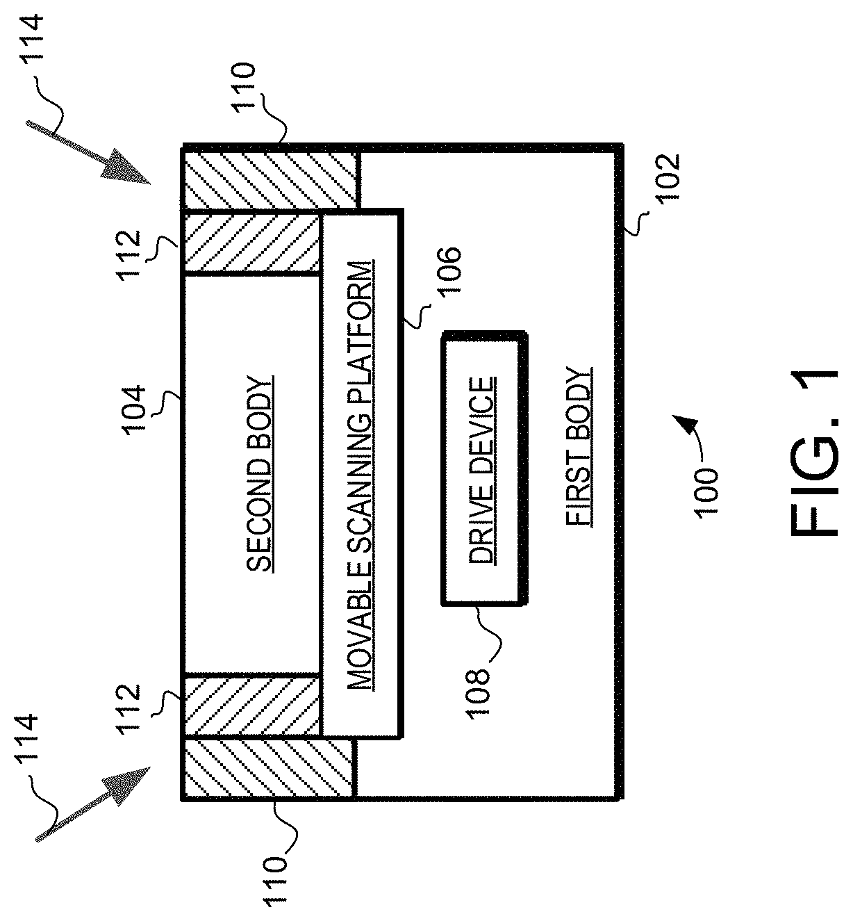
[0015]The embodiments described herein provide scanner assemblies for use in scanning laser devices, including scanning laser projectors, laser depth scanners, LIDAR systems, 3D motion sensing devices, gesture recognition devices, etc. Examples of such scanning laser projectors include traditional image projectors, head-up displays (HUD), and helmet mounted displays (HMD). The scanner assemblies are particularly applicable to scanning laser devices that use microelectromechanical system (MEMS) scanning platforms to facilitate mirror motion. In such devices, the embodiments described herein can facilitate improved yields, reduced costs, and increased performance in the manufacturing of scanner assemblies. Thus, the embodiments described herein can facilitate low cost and high performance scanning laser devices.

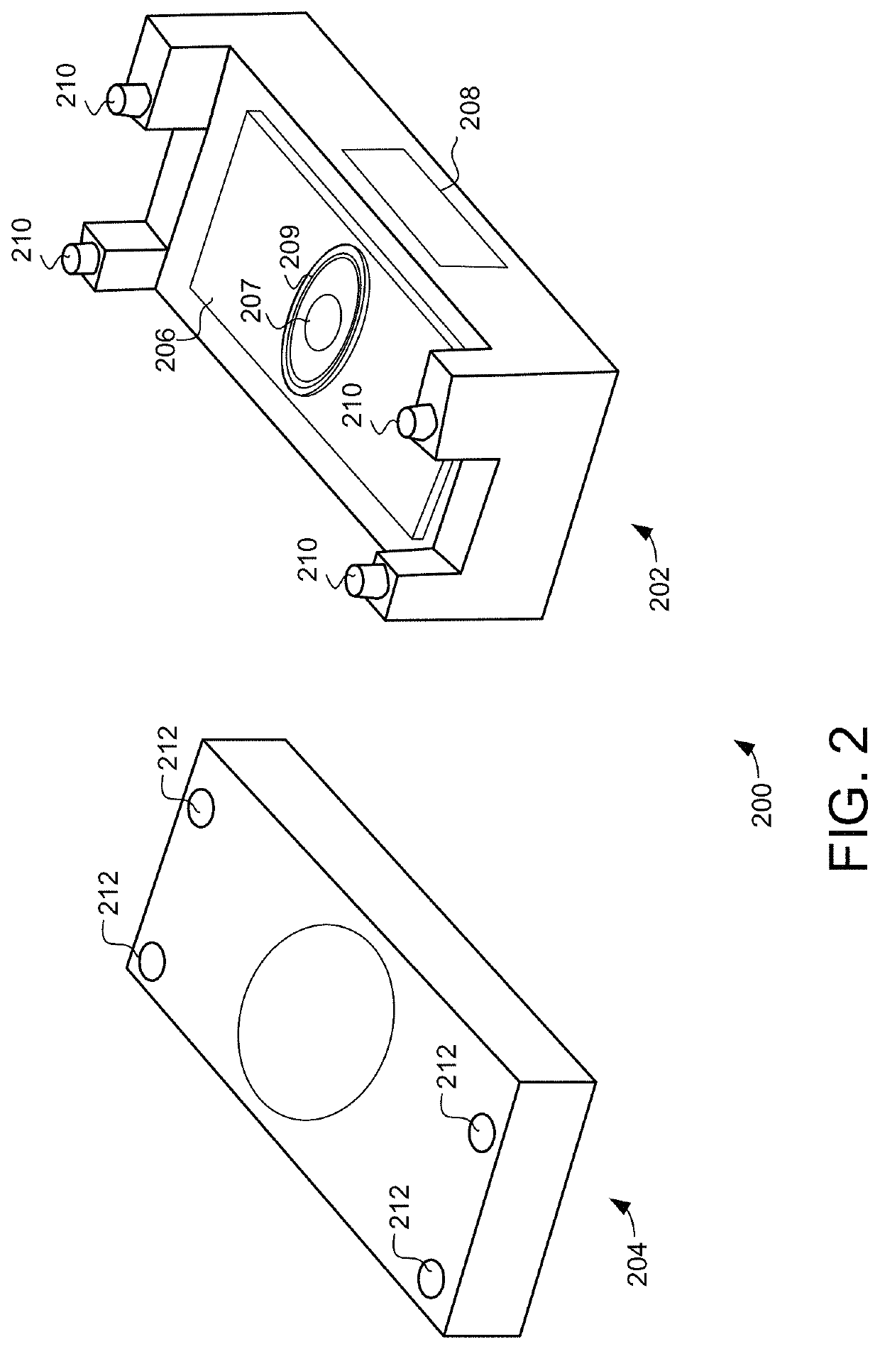
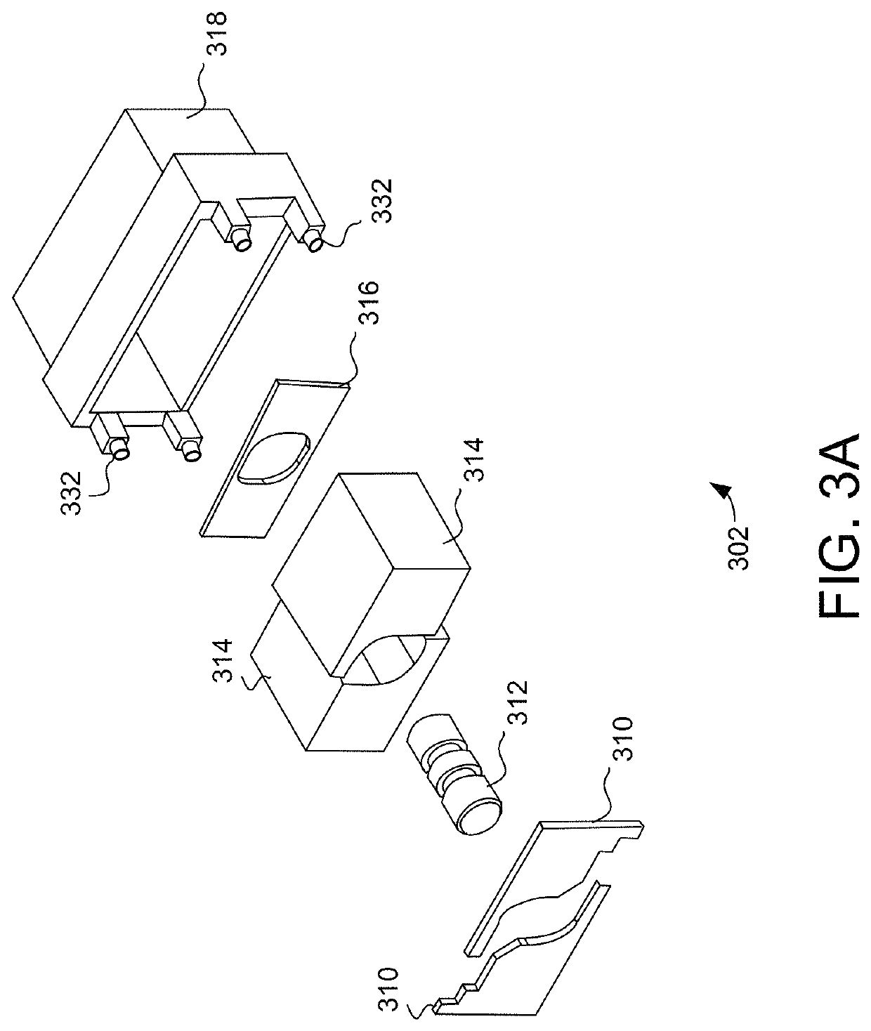
[0016]In accordance with the embodiments described herein scanner assemblies are provided that include a first plastic body, a second plastic body, a movable scanning platform ...


PUM


Abstract

The embodiments described herein provide improved scanner assemblies that include a first plastic body, a second plastic body, a movable scanning platform and a drive device. The first plastic body includes a first plurality of coupling structures, while the second plastic body includes a second plurality of coupling structures. The moveable scanning platform is positioned between the first plastic body and the second plastic body, and each of the first plurality of coupling structures is welded to a corresponding one of the second plurality of coupling structures.

Description

RELATED APPLICATIONS[0001]This application is related to the application entitled “Plastic Laser Welding with Partial Masking” filed on Dec. 19, 2017 with the application Ser. No. 15 / 846,701 and assigned to the same assignee.FIELD[0002]The present disclosure generally relates to scanning laser devices, and more particularly relates to scanning assemblies used in scanning laser devices.BACKGROUND[0003]In scanning laser devices, laser light is reflected off one or more scanning mirrors. Scanning laser projectors and laser depth scanners are two examples of scanning laser devices. In scanning laser projectors, images are projected by scanning laser light into a pattern with a scanning mirror, with individual pixels generated by modulating the laser light. Similarly, laser depth scanners generate depth maps by scanning laser light into a pattern with a scanning mirror and measuring depth based on the reflections of the laser light.BRIEF SUMMARY OF THE INVENTION[0004]Scanner assemblies a...

Claims


Application Information

Patent Timeline
IPC IPC(8): G02B26/08H04N9/31G02B26/10
CPCH04N9/3129G02B26/085G02B26/0858G02B26/105
Inventor BYEMAN, THOMASYUE, NAILISHARMA, SUMIT
Owner MICROVISION
Features
  • Generate Ideas
  • Intellectual Property
  • Life Sciences
  • Materials
  • Tech Scout
  • Unparalleled Data Quality
  • Higher Quality Content
  • 60% Fewer Hallucinations
Learn More