Heat exchanger

a heat exchanger and heat exchange medium technology, applied in indirect heat exchangers, lighting and heating apparatuses, laminated elements, etc., can solve the problems of inability to secure a wide heat transfer area, increase the volume of the heat exchanger, and inability to increase the heat exchanger volume. , to achieve the effect of maximizing the heat exchange efficiency between the heating medium and the combustion gas

Active Publication Date: 2020-03-24
KYUNGDONG NAVIEN
View PDF13 Cites 1 Cited by
  • Summary
  • Abstract
  • Description
  • Claims
  • Application Information

AI Technical Summary

Benefits of technology

[0012]In accordance with a heat exchanger of the present invention, a plurality of unit plates manufactured in similar patterns are stacked to integrally form a latent heat portion having multiple parallel heating paths and a sensible heat portion having serial heating medium flow paths, so that flow resistance of a heating medium is reduced and a maximally long flow path for the heating medium is formed in a limited space such that heat efficiency between the heating medium and a combustion gas can be maximized.

Problems solved by technology

However, in the conventional condensing type heat exchanger, there is a problem in that a volume of the heat exchanger is increased due to the blower being disposed above the housing and the structures of the sensible heat exchanger and the latent heat exchanger which are individually installed inside the housing.
The heat exchanger disclosed in the above-described patent has problems in that the tube is deformed into a rounded shape when the tube is formed into a flat shape and a pressure is applied to a heat transfer medium portion, and a thickness of the tube is to be thick since the tube is manufactured by being rolled up.
Further, the conventional heat exchanger is configured with a structure in which a heat exchange tube is wound around a combustion chamber in the form of a coil, and a heating medium flows in only one direction along the heat exchange tube such that there is a disadvantage of being unable to secure a wide heat transfer area since a heat exchange between a combustion gas and the heating medium is performed only in a local space formed around the heat exchanger in the form of a coil.

Method used


Image

  • Heat exchanger
  • Heat exchanger
  • Heat exchanger

Examples


Embodiment Construction

[0034]Hereinafter, configurations and operations for preferred embodiments of the present disclosure will be described in detail with reference to the accompanying drawings.

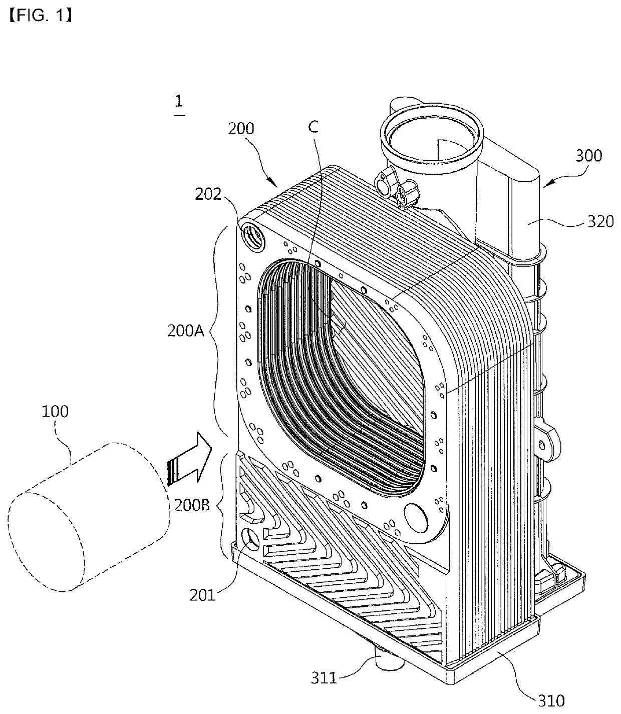
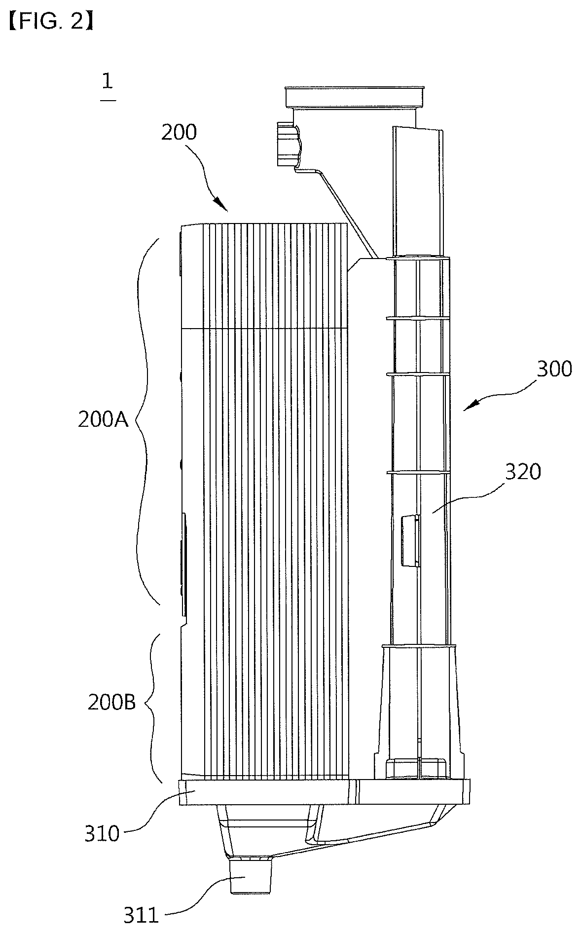
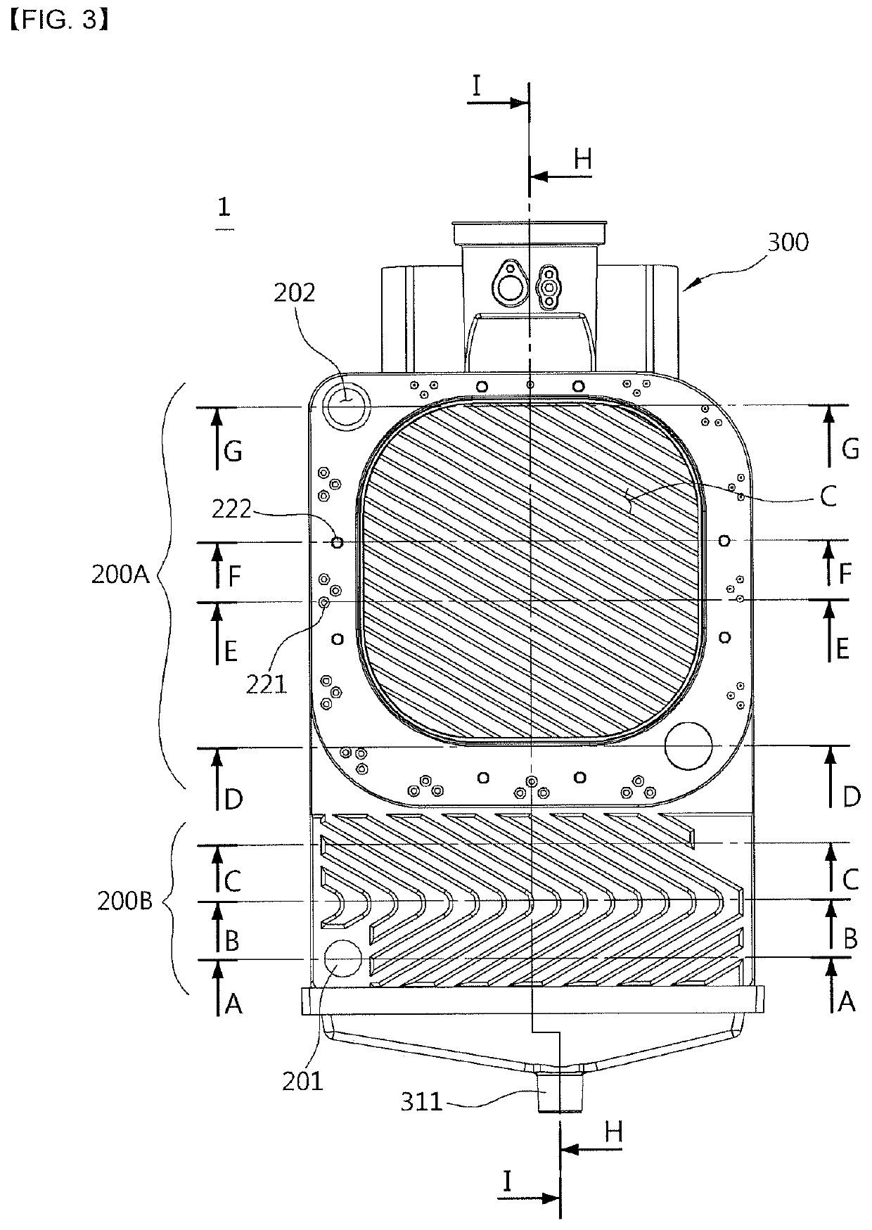
[0035]Referring to FIGS. 1 to 6, a heat exchanger 1 according to one embodiment of the present invention includes a burner 100 configured to combust a mixture of air and fuel to generate combustion heat and a combustion gas; a heat exchange portion 200 provided at a circumference of the burner 100 to perform a heat exchange between a heating medium and the combustion gas generated by the combustion in the burner 100, and constituted by stacking a plurality of plates; and a combustion gas discharge portion 300 configured to discharge a combustion gas which passes through the heat exchange portion 200.

[0036]The burner 100 is a cylindrical burner and is assembled by being inserted into a space of a combustion chamber C provided at the heat exchange portion 200 in a horizontal direction at a front surface, thereby im...


PUM


Abstract

A heat exchanger according to the present invention comprises a heat exchange portion in which heating medium flow paths, where a heating medium flows through a space between a plurality of plates, and combustion gas flow paths through which a combustion gas combusted in a burner flows are adjacently and alternatingly formed, wherein the heat exchange portion comprises a sensible heat portion, which surrounds the outside of a combustion chamber and comprises an area on one side of the plates, for heating the heating medium using the sensible heat of the combustion gas generated by combustion of the burner, and a latent heat portion, which comprises an area on the other side of the plates, for heating the heating medium using the latent heat of water vapors in the combustion gas which has completed heat exchanging in the sensible heat portion, wherein a connection passage for the heating medium is formed between the sensible heat portion and the latent heat portion, the latent heat portion comprises a heating medium inlet through which the heating medium is introduced, and a plurality of latent heat portion heating medium flow paths which are formed between the plurality of plates and communicate with the heating medium inlet in parallel, and wherein the sensible heat portion comprises a heating medium outlet through which the heating medium is discharged, and a plurality of sensible heat portion heating medium flow paths which are formed between the plurality of plates and are connected serially between the latent heat portion heating medium flow paths and the heating medium outlet.

Description

CROSS-REFERENCE TO RELATED APPLICATIONS[0001]This application is a national stage of International Application No. PCT / KR2016 / 008845, filed Aug. 11, 2016, which claims the benefit of Korean Application No. 10-2015-0121959, filed Aug. 28, 2015, in the Korean Intellectual Property Office, the disclosures of which are incorporated herein in their entireties by reference.TECHNICAL FIELD[0002]The present invention relates to a heat exchanger, and more particularly, to a heat exchanger having a simplified assembly structure due to stacking of a plurality of unit plates to integrally form a sensible heat portion and a latent heat portion, and capable of securing a wide heat transfer area between a heating medium and a combustion gas by reducing flow resistance of the heating medium and forming a long flow path for the heating medium in a limited space.BACKGROUND ART[0003]A boiler used for heating or warm water is a device configured to heat a desired area or supply warm water by heating wa...

Claims


Application Information

Patent Timeline
Patent Type & Authority Patents(United States)
IPC IPC(8): F24H1/34F24H8/00F24H1/32F24H1/30F24H1/44F28D21/00F28F3/04F28F3/00F28D20/02F28D9/00F28F3/02F24H9/00
CPCF24H8/00F24H1/44F28D20/02F24H1/32F24H1/445F24H1/34F28D9/00F28D21/00F28F3/04F24H1/30F28F3/00F28F3/046F28F3/025F24H9/0015F28D21/0007F28D9/005Y02B30/00Y02E60/14
Inventor JEONG, INCHUL
Owner KYUNGDONG NAVIEN
Why Eureka
Try Eureka