Separation device

a separation device and a technology of a sieve, applied in the direction of separation process, filtration separation, papermaking, etc., can solve the problems of increasing the flow above the shaft, the prior art device is not good for this kind of separation, etc., and achieves the effect of reducing the tendency of the disc, thus energy consumption, and reducing the flow resistance through the siev

Active Publication Date: 2022-05-10
ANDRIZ OY
View PDF24 Cites 0 Cited by
  • Summary
  • Abstract
  • Description
  • Claims
  • Application Information

AI Technical Summary

Benefits of technology

[0005]The new separation device has a considerably low power demand and flow resistance and structures that are prone to wearing and breaking are avoided. The separation device is also characterized in accepting three-dimensional pieces of a certain kind and degrading of pieces for being acceptable. Differing from conventional solutions, the rotor unit of the separation device has a shaft transverse with respect to the through-flow direction of the separation device, which shaft rotates discs attached to the shaft, which discs are solid or open in their center and have on their outer surface and / or side surfaces notches or protrusions that make said surface jagged. A jagged surface is also understood as a substantially coarse surface, such as knurling, corrugation or roughening, which is especially advantageous on the side surfaces of the discs. The teeth of at least two sieves attached to the housing extend between the discs, the first of which sieves is between the reject conduit and the accept conduit and the second sieve is between the feed conduit and the accept conduit.

Problems solved by technology

Prior art devices are not good for this kind of separation.
Even a partial clogging caused by rejectable pieces in the first sieve leads also to increased flow above the shaft through the second sieve.

Method used


Image

  • Separation device
  • Separation device
  • Separation device

Examples


Embodiment Construction

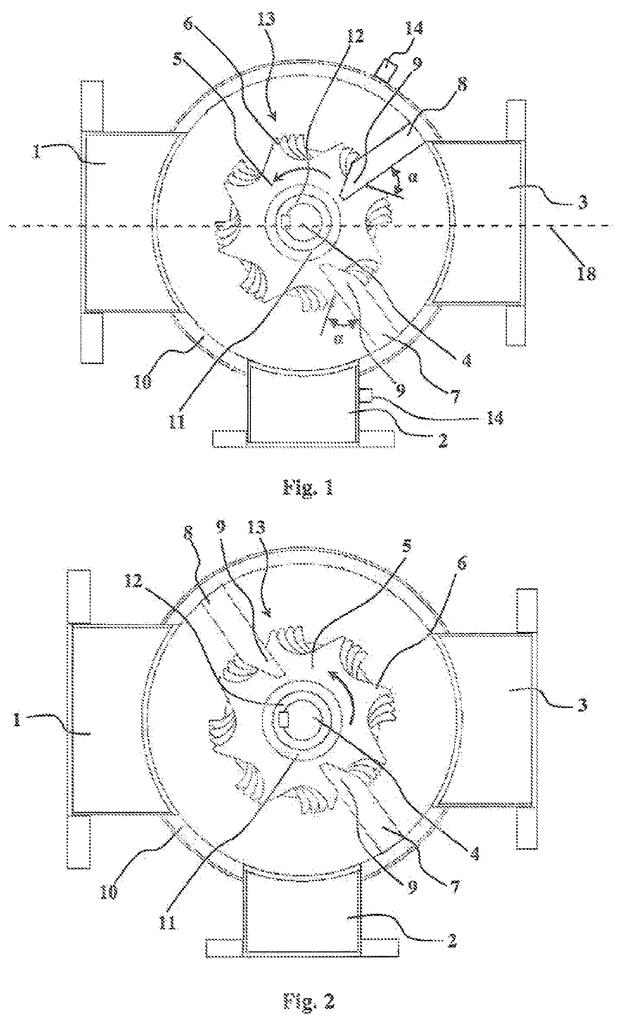
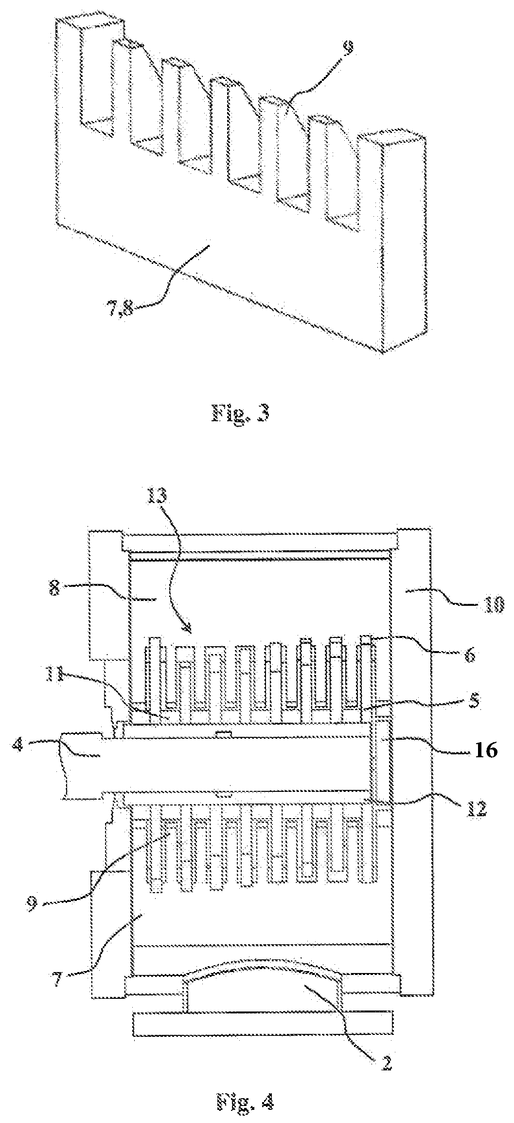
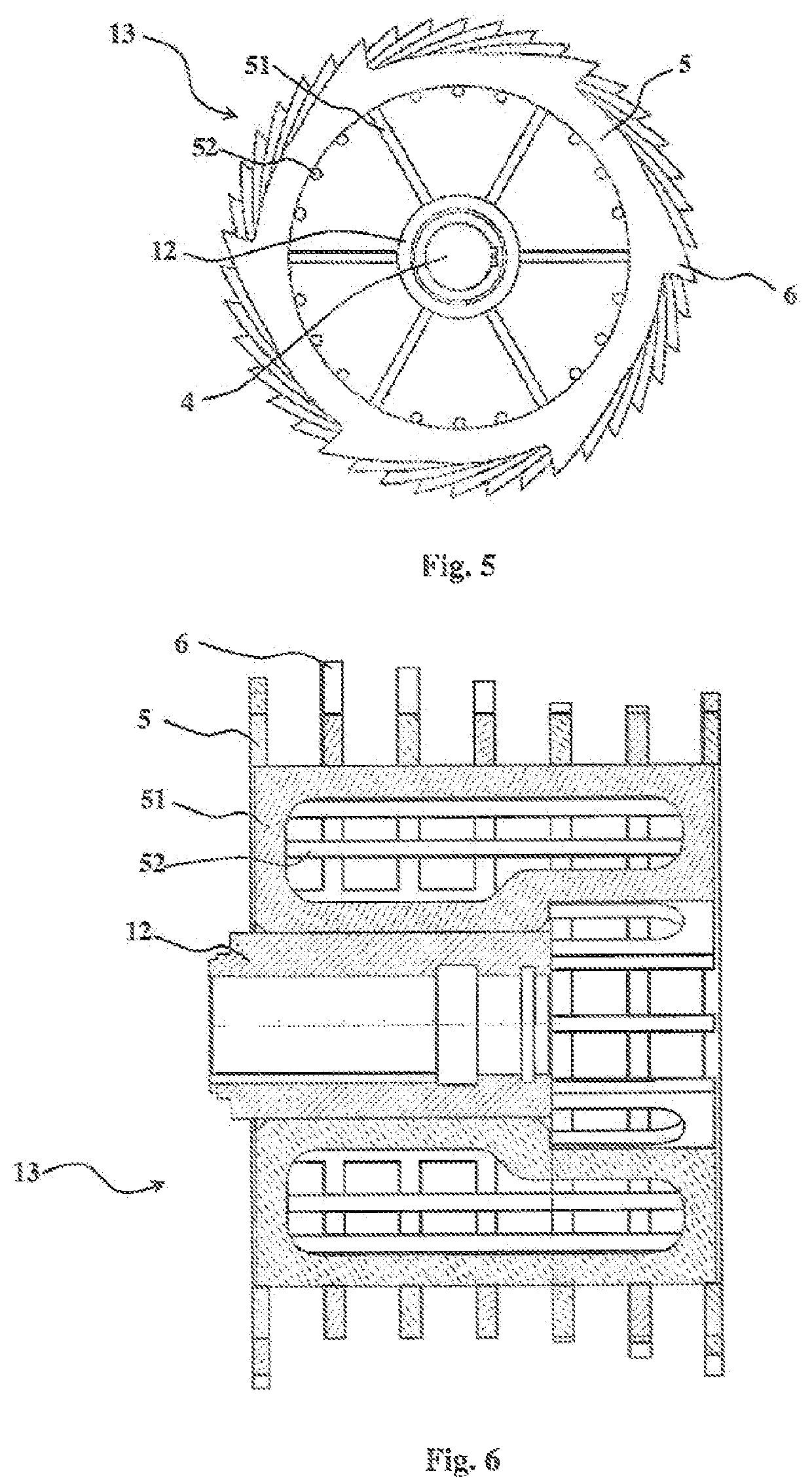
[0026]FIG. 1 illustrates a preferred embodiment of the separation device having a housing 10 with a feed conduit 1 and a reject conduit 2, between which conduits 1 and 2 and an accept conduit 3 a rotor unit 13 is arranged. The rotor unit 13 has a shaft 4 transverse with respect to the through-flow direction, which shaft 4 rotates discs 5 attached to the shaft 4, and at least two sieves 7 and 8. The feed conduit 1 and accept conduit 3 are aligned such that a straight line 18 perpendicular to a rotational axis of the shaft 4 extends through the feed and accept conduits. The shaft 4 is advantageously in horizontal position. The outer surface of the discs 5 is provided with protrusions 6. Between the discs 5 there may be support sleeves 11, which keep their distances equal. More advantageous direction of rotation is marked in the Figure. The rotational speed of the discs 5 is advantageously between 200-1000 rpm. Advantageously at least some protrusions 6 of different discs 5 are at vari...


PUM

PropertyMeasurementUnit
angleaaaaaaaaaa
angleaaaaaaaaaa
heightaaaaaaaaaa

Abstract

A separation device having a housing (10) with a feed conduit (1) and a reject conduit (2), between which conduits (1, 2) and an accept conduit (3) of the housing (10) is a rotor unit (13) having a shaft (4) transverse to the through-flow direction of the separation device, which shaft rotates discs (5) attached to the shaft (4), the outer surface and / or side surfaces of which discs are jagged, i.e. they have protrusions (6) and / or notches and / or these surfaces are substantially rough and the teeth (9) of at least two sieves (7, 8) attached to the housing (10), extend between the discs (5), the first sieve (7) being between the reject conduit (2) and the accept conduit (3) and the second sieve (8) being between the feed conduit (1) and the accept conduit (3).

Description

[0001]This application is the U.S. national phase of International Application PCT / FI2018 / 050616 filed Aug. 31, 2018, which designated the U.S. and claims priority to Finnish Patent Application 20175776 filed Aug. 31, 2017, the entire contents of both applications is incorporated by reference.[0002]The invention relates to a separation device for separating oversize pieces from liquid and solids containing suspension, such as cellulose suspension.BACKGROUND OF THE INVENTION[0003]The equipment and processes of the cellulose and paper industry usually endure some amount of different impurities, such as sand, but the feed material may contain larger pieces such as stones, bolts etc. metal pieces. Fibrous pieces can often be utilized and defibrated in later process stages, as long as they do not hamper the operation of the equipment. The aim is to keep the feed pulp at a high concentration, due to which it contains pieces, which at a lower concentration would remain on the bottom of the...

Claims


Application Information

Patent Timeline
Patent Type & Authority Patents(United States)
IPC IPC(8): B07B13/00D21D5/06
CPCB07B13/003D21D5/06B07B2230/01D21B1/026D21D5/20B01D29/00B01D29/64D21D5/00
Inventor PELTONEN, KARIVEHMAA, JANNEKAIPAINEN, VESASIIK, SAMIPORKKA, SAMPSA
Owner ANDRIZ OY
Why Eureka
Try Eureka