Multiple oscillating water pumping device

a pumping device and multi-oscillating technology, which is applied in the direction of machines/engines, liquid fuel engines, positive displacement liquid engines, etc., can solve the problems of deteriorating usability, difficulty in maintaining the water pumping device installed in the water, and difficulty in installing the propeller type rotation means on shore or near the underwater structure, so as to minimize the supply of power source, prevent the effect of water pumping efficiency deterioration, and minimize the loss of the head

Active Publication Date: 2020-03-31
KOREA INST OF OCEAN SCI & TECH KIOST
View PDF18 Cites 0 Cited by
  • Summary
  • Abstract
  • Description
  • Claims
  • Application Information

AI Technical Summary

Benefits of technology

[0010]An aspect of the present disclosure is to provide a multiple oscillating water pumping device configured to minimize the supply of a power source required for an operation and to minimize the loss of head in a process in which pumped water flows toward a reservoir along a conduit.
[0011]Another aspect of the present disclosure is to provide a multiple oscillating water pumping device that prevents water pumping efficiency from being deteriorated by interference with rain or wind while only the minimum number of elements that generate a lifting force using flow energy are disposed in fluid.
[0015]The first cylinder may include: a body in which the first piston is configured to reciprocate; an intake part connected with the body and having a first check valve installed therein for preventing fluid from flowing out of the body when the internal pressure of the first cylinder increases; and a discharge part connected with the body and having a second check valve installed therein for preventing fluid from flowing into the body when the internal pressure of the first cylinder decreases.
[0020]Accordingly, the present disclosure may provide a multiple oscillating water pumping device in which an interlocking unit transmits the rotating force of an arm at one side to a rotating shaft of a wing member at the other side, thereby minimizing the supply of a power source required for an operation.
[0021]Further, the present disclosure may provide a multiple oscillating water pumping device in which one pair of first connecting rods, on opposite sides of the first pivot shaft, is rotatably coupled with the first arm, thereby minimizing the loss of head in a process in which pumped water flows toward a reservoir along a conduit.
[0022]In addition, the present disclosure may provide a multiple oscillating water pumping device in which the rotating shaft of the first wing member is rotatably coupled with the first arm outside fluid so that it is possible to prevent water pumping efficiency from being deteriorated by interference with rain or wind while only the minimum number of elements that generate a lifting force using flow energy are disposed in the fluid.

Problems solved by technology

However, the conventional water pumping device disclosed in KR Patent No. 10-0937338 has to drive a lifting pump, so its usability is degraded on account of the difficulty in consistently supplying a power source (such as, oil fuel, etc.) required for driving a lifting pump and a generator to islands or marine structures with restricted accessibility.
Although the tidal energy system disclosed in EP Patent No. 1979610 drives a water pumping device by rotating a propeller type rotation means using the flow energy of the tide, it is difficult to install the propeller type rotation means on shore or near an underwater structure since the rotation means has to be completely submerged in the water.
Further, since the water pumping device is installed to be submerged in the water, high water tightness is required for the water pumping device, and even though the water pumping device is installed in the water, there may be difficulty in maintaining the water pumping device installed in the water.

Method used


Image

  • Multiple oscillating water pumping device
  • Multiple oscillating water pumping device
  • Multiple oscillating water pumping device

Examples


Embodiment Construction

[0030]Hereinafter, exemplary embodiments of the present disclosure will be described in detail with reference to the accompanying drawings. In the description of the present disclosure, the description of the well-known function or structure will be omitted in order to clear the subject matter of the present disclosure.

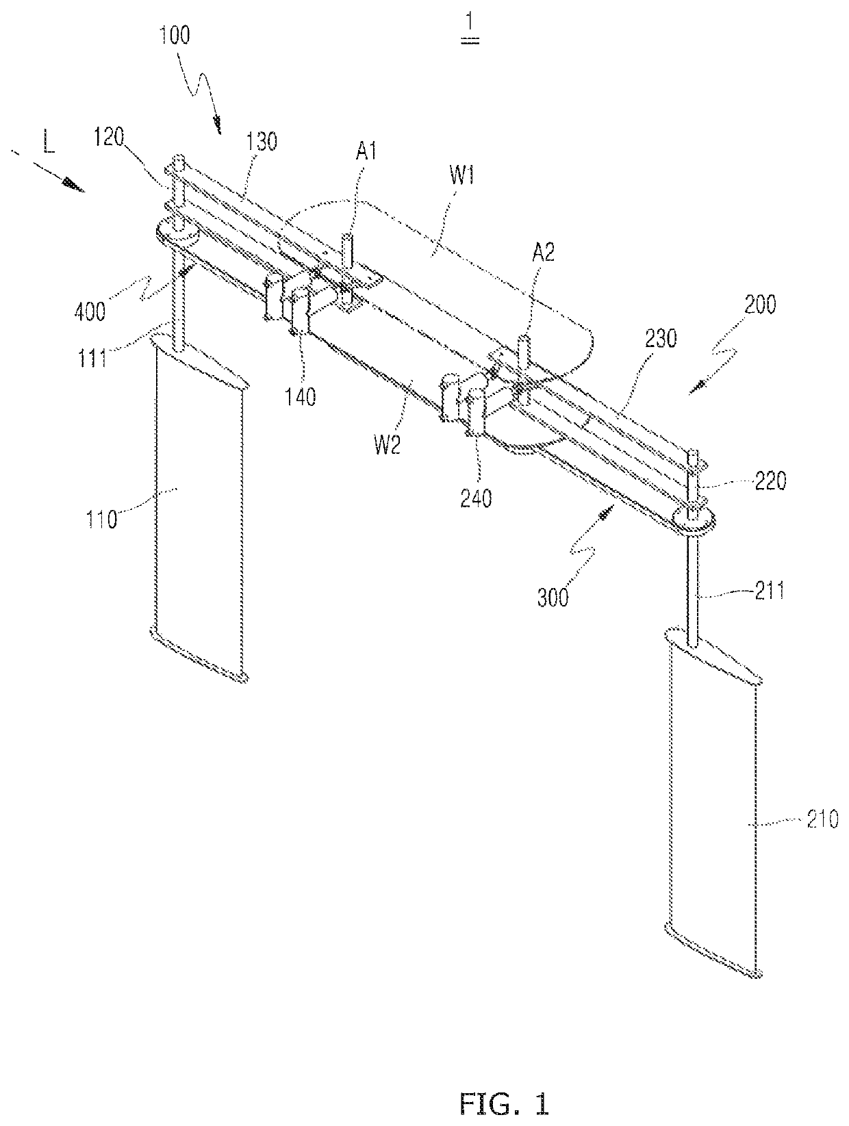
[0031]A multiple oscillating water pumping device of the present disclosure is configured to minimize the supply of a power source required for an operation and to minimize the loss of head in a process in which pumped water flows toward a reservoir along a conduit.

[0032]In addition, a multiple oscillating water pumping device of the present disclosure is configured to prevent water pumping efficiency from being deteriorated by interference with rain or wind while only the minimum number of elements that generate a lifting force using flow energy are disposed in fluid.

[0033]FIG. 1 is a perspective view of a multiple oscillating water pumping device according to an emb...


PUM


Abstract

A multiple oscillating water pumping device includes: a wing member disposed in fluid to generate a lifting force using the flow energy of the fluid; a rotation device to reciprocally rotate the wing member to periodically change the direction of the lifting force acting on the wing member; an arm is rotatably coupled to the wing member, the arm being reciprocally rotated about a pivot shaft by the lifting force acting on the wing member; and a cylinder where fluid enters and exits according to the internal pressure that is periodically increased and decreased by the reciprocating motion of a piston that is connected with the arm through a connecting rod. The multiple oscillating water pumping device is configured to minimize the supply of a power source required for operation and to minimize the loss of head when pumped water flows toward a reservoir along a conduit.

Description

CROSS REFERENCE TO RELATED APPLICATIONS[0001]This application claims priority to Korean Patent Application No. 10-2015-0153972, filed Nov. 3, 2015, the contents of such application being incorporated by reference herein.BACKGROUND OF THE INVENTION1. Field of the Invention[0002]The present disclosure relates to a multiple oscillating water pumping device, and more specifically, to a multiple oscillating water pumping device configured such that the supply of a power source required for an operation is minimized and only the minimum number of elements that generate a lifting force using flow energy are disposed in fluid.2. Description of the Prior Art[0003]Water pumping devices refer to facilities that push up water with a pump from a water reservoir at a low level to a water reservoir at a high level. Water pumping devices are mainly used for industrial or agricultural purposes. In particular, water pumping devices are essential for islands or boring facilities that urban infrastruct...

Claims


Application Information

Patent Timeline
Patent Type & Authority Patents(United States)
IPC IPC(8): F04B17/06F03B13/26F04B53/16F04B17/00F04B19/22F04B23/06F04B53/10F04B53/14F03D9/28F03D5/06F03B17/06
CPCF03D5/06F04B19/22F04B17/06F04B17/00F03B17/06F04B53/10F03B13/264F04B53/14F04B23/06F03D9/28F04B53/16Y02E10/70F05B2210/16Y02E10/28Y02E10/72Y02E10/30Y02E10/20
Inventor KO, JIN HWANSITORUS, PATAR EBENEZERPARK, JIN SOON
Owner KOREA INST OF OCEAN SCI & TECH KIOST
Why Eureka
Try Eureka