Device and method for liquefying a natural gas and ship comprising such a device

a technology of natural gas and liquefying device, which is applied in the direction of liquefaction, solidification, cold treatment separation, etc., to achieve the effect of reducing the energy supply of the system for liquefying

Inactive Publication Date: 2019-10-10
GDF SUEZ SA
View PDF0 Cites 0 Cited by
  • Summary
  • Abstract
  • Description
  • Claims
  • Application Information

AI Technical Summary

Benefits of technology

[0088]Use of such a mixture makes it possible to minimize the energy supply to the system for liquefying the natural gas.
[0089]In effect, in the CII system as currently implemented,

Problems solved by technology

Implementation of the technologies thus used requires very substantial investments and has very high transportation costs (marine liquefaction and reception facilities).
However, these opportunities are too small to justify the use of technologies intended for large-scale production (the transposition of conventional technologies is not appropriate, as they are too complex and cannot be used to support the economic viability of these technologies), hence the need to propose new technologies that can meet the two main challenges relating to liquefaction on a small scale:reducing investment costs as much as possible while keeping efficiency as high as possible in order to minimize operating costs; andincreasing the efficiency of the method so as to minimize product loss: the gas volumes to be upcycled are small, which makes every molecule important.
This system has several drawbacks:plate heat exchangers are very sensitive to the distribution of fluids, which poses a problem of marine adaptation for the marine applications;the coolant mixture has a significant number of components, especially heavy compounds, and these compounds crystallize in the heat exchangers under particular pressure and temperature conditions whose arrival is difficult to forecast; andthe method has limited flexibility, especially in terms of operating flow rate, and a limited production capacity per compression means.
For the CII system the main drawbacks are that:the CII method had been developed for large-scale LNG production on land;the method is not very flexible: efficiency drops significantly with any deviation from the operating/design point;the coolant mixture contains too many constituents (hydrocarbons), making the logistics and operational aspect more complex;storage increases the weight of the facilities, critical for offshore facilities;the method has difficulties concerning the ethane supply, which poses significant difficulties for offshore facilities;the method presents risks of alteration to the equipment (exchangers) due to the risk of crystallization of the pen

Method used


Image

  • Device and method for liquefying a natural gas and ship comprising such a device
  • Device and method for liquefying a natural gas and ship comprising such a device
  • Device and method for liquefying a natural gas and ship comprising such a device

Examples


Embodiment Construction

OF REALIZATION OF THE INVENTION

[0117]The present description is given in a non-limiting way, each characteristic of an embodiment being able to be combined with any other characteristic of any other embodiment in an advantageous way.

[0118]It is now noted that the figures are not to scale.

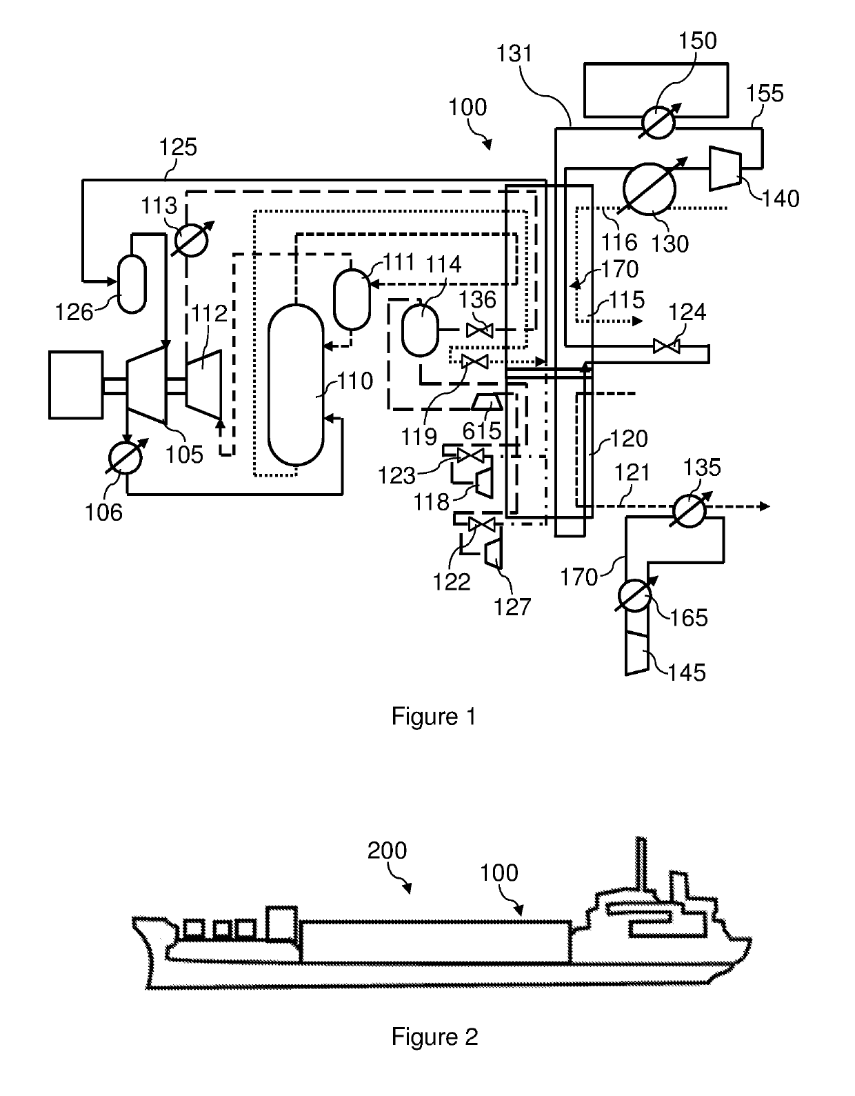
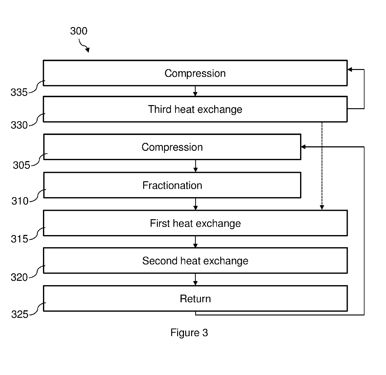
[0119]FIG. 1, which is not to scale, shows a schematic view of an embodiment of the device 100 that is the subject of the present invention. This device 100 for liquefying a natural gas comprises:[0120]a compressor 105 of a first vaporized coolant chemical mixture,[0121]a means 110 for fractionating the compressed mixture into a heavy fraction and a light fraction,[0122]a first body 115 for exchanging heat between the heavy fraction of the first mixture and the natural gas in order to cool at least the natural gas,[0123]a second body 120 for exchanging heat between the light fraction of the first mixture and the natural gas cooled in the first exchange body to liquefy the natural gas,[0124]a conduit...


PUM


Abstract

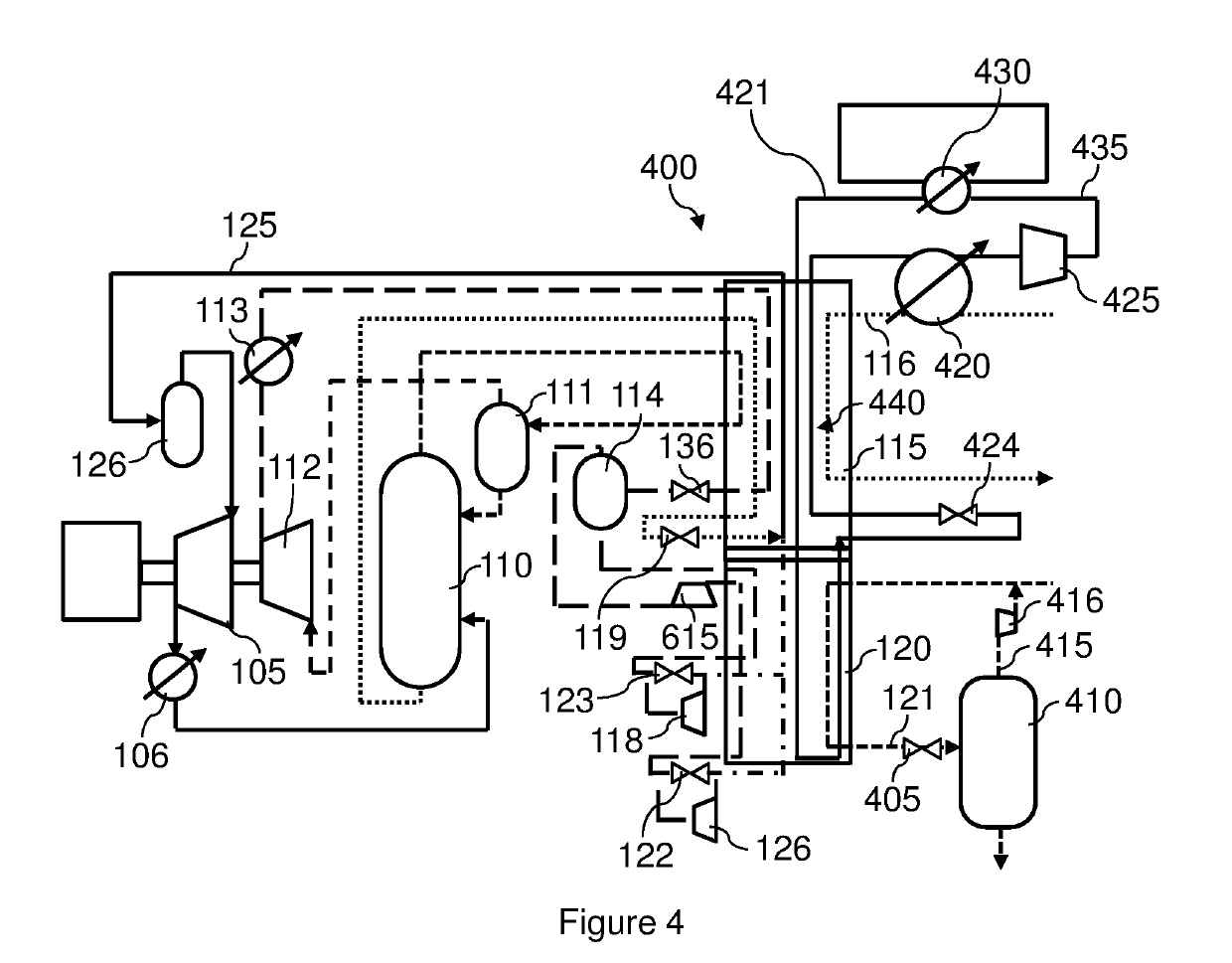
The device (400) for liquefying a natural gas comprises: a compressor (105) of a first vaporized coolant chemical mixture, a means (110) for fractionating the compressed mixture into a heavy fraction and a light fraction, —a first body (115) for exchanging heat between the heavy fraction of the first mixture and the natural gas to cool at least the natural gas, a second body (120) for exchanging heat between the light fraction of the first mixture and the natural gas cooled in the first exchange body to liquefy the natural gas, —a conduit (125) for returning the first vaporized coolant mixture in the heat exchange bodies to the compressor, —a regulator (405) for the liquefied natural gas, a collector (410) for the evaporation gas produced during the expansion of the gas in the regulator, —a conduit (415) for injecting the evaporation gas at the inlet of the second exchange body, upstream of an inlet (116) for the natural gas in the first exchange body (115), a third body (420) for exchanging heat between the natural gas and a second chemical coolant compound, —a means (425) for compressing the second vaporized compound, a means (430) for cooling the second compressed compound and a conduit (435) for transferring the second cooled compound towards the third exchange body.

Description

TECHNICAL FIELD OF THE INVENTION[0001]The present invention relates to a device for liquefying a natural gas, a method for liquefying a natural gas, and a ship comprising such a device. It applies, in particular, to the offshore or onshore liquefaction of natural gas.STATE OF THE ART[0002]Liquefying the gas allows natural gas to be transported in a smaller volume compared to transporting non-liquefied natural gas.[0003]Over the last few decades, liquefaction technologies have focused on large gas capacities for reasons of economy of scale.[0004]Implementation of the technologies thus used requires very substantial investments and has very high transportation costs (marine liquefaction and reception facilities). As a result, firstly the trend for liquefaction capacities has been to increase the volume of natural gas transported in order to obtain economies of scale and to make these projects economically more attractive. Secondly, the investments made to implement these technologies ...

Claims


Application Information

Patent Timeline
IPC IPC(8): F25J1/00F25J1/02
CPCF25J1/0057F25J2270/14F25J2245/02F25J1/0278F25J1/0072F25J2230/60F25J1/0022F25J1/029F25J1/0216F25J1/0292F25J1/0055F25J2220/64F25J1/0052F25J1/0215F25J1/0218F25J1/0279F25J1/0283F25J2270/90F25J2210/04
Inventor GUEDACHA, HICHAM
Owner GDF SUEZ SA
Why Eureka
Try Eureka