Apparatus for assembling substrates of planar fluorescent lamp

a fluorescent lamp and apparatus technology, applied in the manufacture of electrode systems, electric discharge tubes/lamps, auxilary welding devices, etc., can solve the problems of poor productivity, drop in working efficiency, damage to the upper substrate and the lower substrate, etc., to achieve the effect of minimizing the supply of substrates

Inactive Publication Date: 2007-12-18
MATHBRIGHT TECH
View PDF18 Cites 0 Cited by
  • Summary
  • Abstract
  • Description
  • Claims
  • Application Information

AI Technical Summary

Benefits of technology

[0015]An object of the present invention is to provide a an apparatus for assembling an upper substrate and a lower substrate of a planar fluorescent lamp, in which the baking process and the assembly process are performed continuously in a state an upper substrate and a lower substrate of the fluorescent lamp are held together, to minimize supply of the substrates to, and drawing out of the substrates from furnace, and enable mass production of the planar fluorescent lamp.
[0016]Another object of the present invention is to provide an apparatus for assembling an upper substrate and a lower substrate of a planar fluorescent lamp, in which, after sealfrit and fluorescent material are baked on surfaces of an upper substrate and a lower substrate, the upper substrate and the lower substrate are assembled without using separate driving means, while preventing the upper substrate and the lower substrate suffer from damage caused by impact during the assembly.

Problems solved by technology

However, the related art planar fluorescent lamp has the following problems in fabrication.
However, the baking process and the assembling process performed separately with separate apparatuses cause to require the upper substrate and the lower substrate fed into, and drawn out of the furnace frequently, not only to drop working efficiency, with consequential poor productivity, but also to cause cases when the upper substrate and the lower substrate are damaged during working, frequently.
Moreover, since there have been no means for continuous fabrication of a plurality of fluorescent lamps in the related art, excessive working time period is required for mass production of the fluorescent lamps.

Method used


Image

  • Apparatus for assembling substrates of planar fluorescent lamp
  • Apparatus for assembling substrates of planar fluorescent lamp
  • Apparatus for assembling substrates of planar fluorescent lamp

Examples


Embodiment Construction

[0029]Reference will now be made in detail to the preferred embodiments of the present invention, examples of which are illustrated in the accompanying drawings. Wherever possible, the same reference numbers will be used throughout the drawings to refer to the same or like parts.

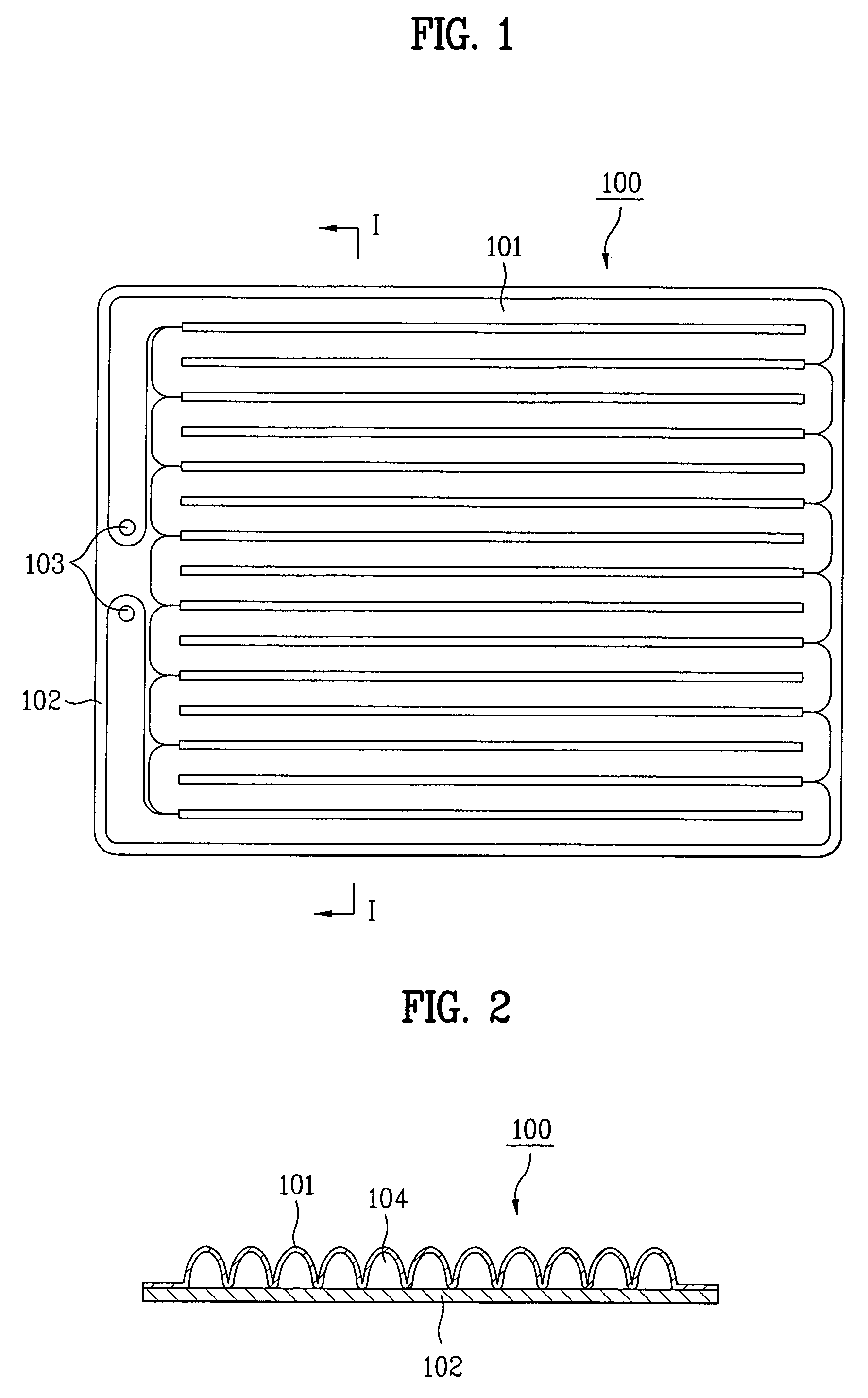
[0030]For convenience of description, with regard to a structure of a planar fluorescent lamp of the present invention, a fluorescent lamp structure shown in FIGS. 1 and 2 will be referred to, and detailed description of which will be omitted.

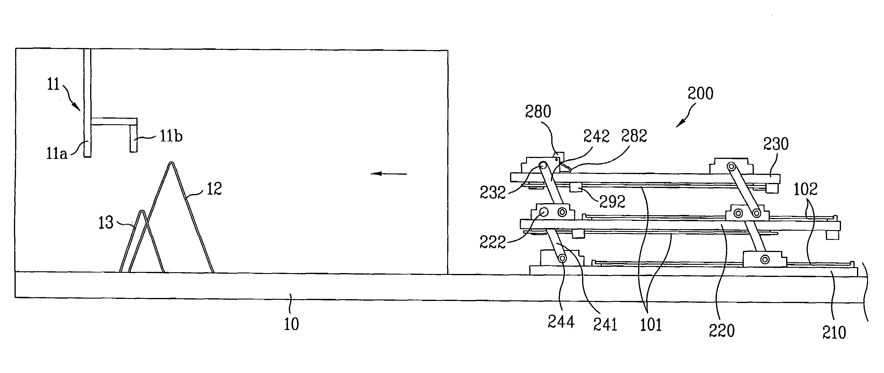
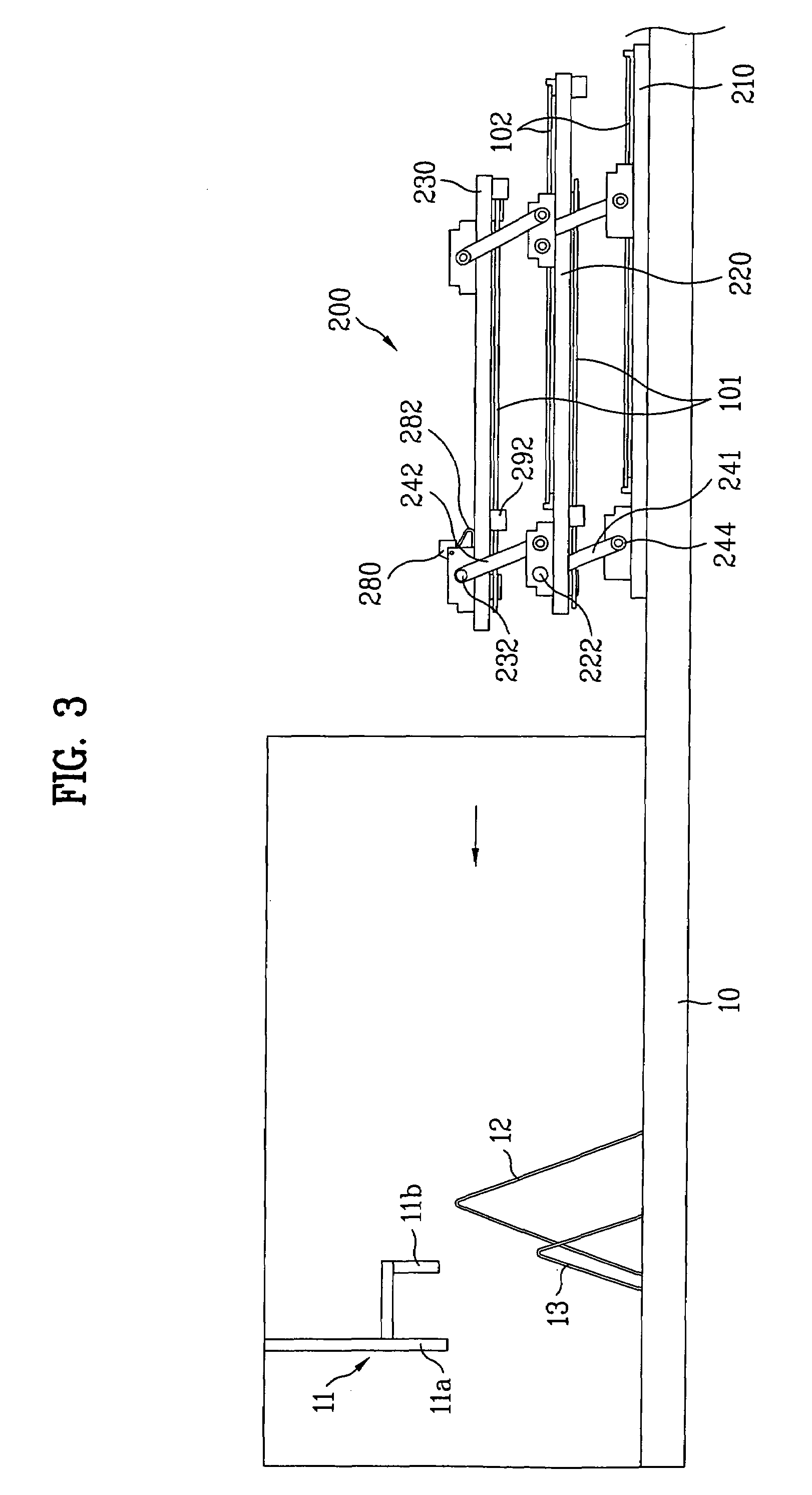
[0031]Referring to FIG. 3, a substrate assembling apparatus (also called as 'assembly jig) 200 is designed to carry an upper substrate 101 and a lower substrate 102 of the fluorescent lamp while being moved along a process line 10 by a carrier of a furnace which performs baking and assembly, to seal, and bond the upper substrate 101 and the lower substrate 102, together.

[0032]The substrate assembly apparatus 200 includes a base 210 movable along the process line 10, a f...


PUM

PropertyMeasurementUnit
movementaaaaaaaaaa
timeaaaaaaaaaa
elastic forceaaaaaaaaaa

Abstract

Apparatus for assembling substrates of a planar fluorescent lamp including a base mounted movable along a process line, the base having an upper surface for placing a first substrate of the fluorescent lamp, at least one movable board over the base, the movable board being mounted rotatable between a first position and a second position, at least one pair of parallel links each having one end rotatably coupled to the base and the other end rotatably coupled to the movable board for the movable board rotatable from the first position to the second position, a plurality of clamping members mounted on the movable board for holding a second substrate of the fluorescent lamp at a position under the movable board, a stopping member mounted in the process line over a direction of movement of the base, for coming into contact with the movable board to cause rotation of the movable board, and a damping member for making a damping action at a time the first, and second substrates of the fluorescent lamp come into contact with each other as the movable board rotates, downwardly.

Description

CROSS-REFERENCE TO RELATED APPLICATIONS[0001]This application claims the benefit of Korean Application No. P2004-76400 filed on Sep. 23, 2004, which is hereby incorporated by reference as if fully set forth herein.BACKGROUND OF THE INVENTION[0002]1. Field of the Invention[0003]The present invention relates to an apparatus for assembling substrates of a planar fluorescent lamp, and more particularly, to an apparatus for assembling an upper substrate and a lower substrate of a planar fluorescent lamp.[0004]2. Discussion of the Related Art[0005]Recently, as a back light unit which is a back side illumination of an LCD panel, use and development of the planar fluorescent lamp, which can provide a high luminance and a high luminance uniformity, increases, rapidly. The planar fluorescent lamp is fabricated by assembling an upper plate of a serpentine shape and a planar lower plate with sealfrit, and coating fluorescent material on an inside space thereof.[0006]An example of the planar flu...

Claims


Application Information

Patent Timeline
Patent Type & Authority Patents(United States)
IPC IPC(8): B32B37/00
CPCH01J9/245H01J61/307H01J9/46H01J9/248
Inventor YUN, JAE DOO
Owner MATHBRIGHT TECH
Why Eureka
Try Eureka