Motor overload protector

a technology for overload protection and motors, applied in relays, lighting and heating apparatuses, refrigeration components, etc., can solve problems such as devices that may not meet requirements, and achieve the effects of reducing excess space, minimizing fuel supply, and reducing space. excess volum

Active Publication Date: 2007-12-04
SENSATA TECH MASSACHUSETTS INC
View PDF21 Cites 0 Cited by
  • Summary
  • Abstract
  • Description
  • Claims
  • Application Information

AI Technical Summary

Benefits of technology

[0008]According to a preferred embodiment of the invention, the cover is modified by forming first and second multiple wall barriers to impede the travel of arcs from the make-and-break contacts. The first multiple wall barrier comprises spaced apart wall portions which are received on the mounting portion of the first terminal closely adjacent to the stationary and movable contacts. According to a feature of the invention, the wall portions form a generally triangular configuration with respect to a cross section taken parallel to the bottom wall of the base. This structure also serves to decrease the volume of space between the base and cover thereby minimizing the supply of fuel to an internal explosion. According to another modification of the cover a vertically extending notch is formed in the walls which interfit with a corner portion of a corresponding side wall of the base to further inhibit arc travel. The second multiple wall barrier comprises another set of spaced apart wall portions along the perimeter of the base at a side of the first end of the recess to limit travel of arcing from the contacts and to further decrease excess volume of space. In another preferred embodiment of the invention, the various openings formed in the housing of the device are sealed by epoxy to prevent propagation of any internal explosion from external flammable gas. The sealing can be utilized by itself or along with the cover modifications noted above.

Problems solved by technology

However, such devices may not meet the requirement of the second edition IEC Standard 60079-15, which requires that an enclosed break device pass a make-and-break test 10 times.

Method used


Image

  • Motor overload protector
  • Motor overload protector
  • Motor overload protector

Examples


Embodiment Construction

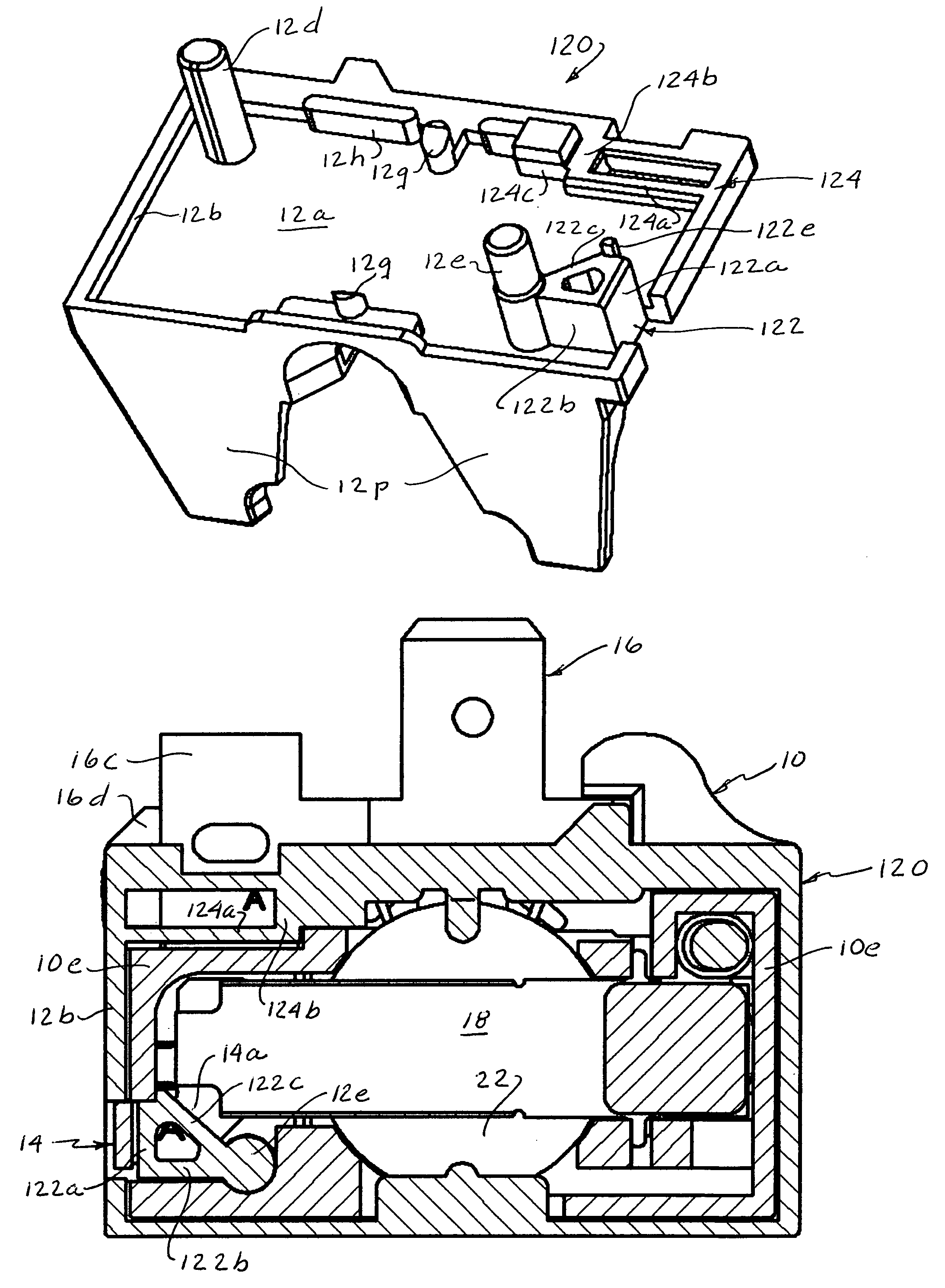
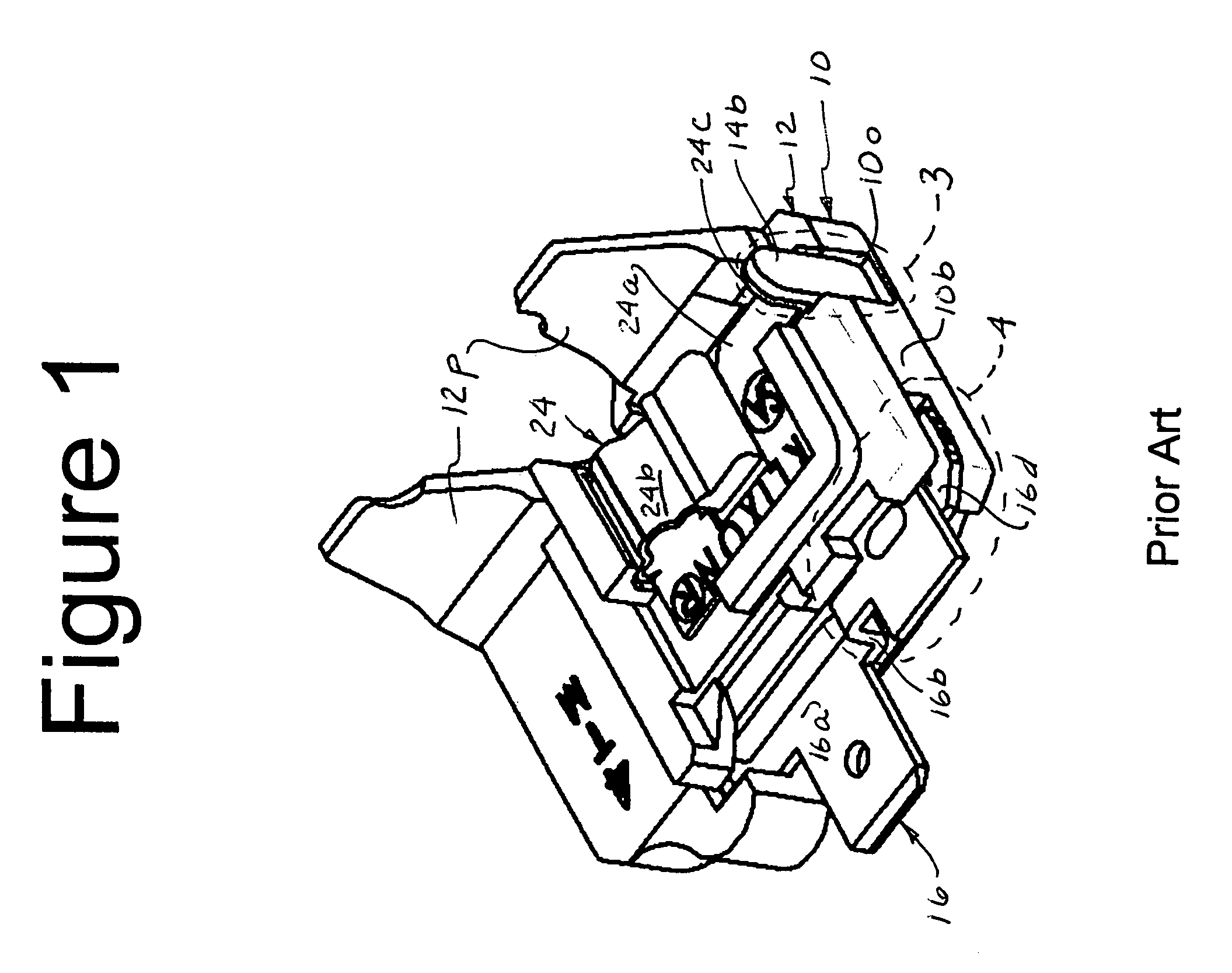
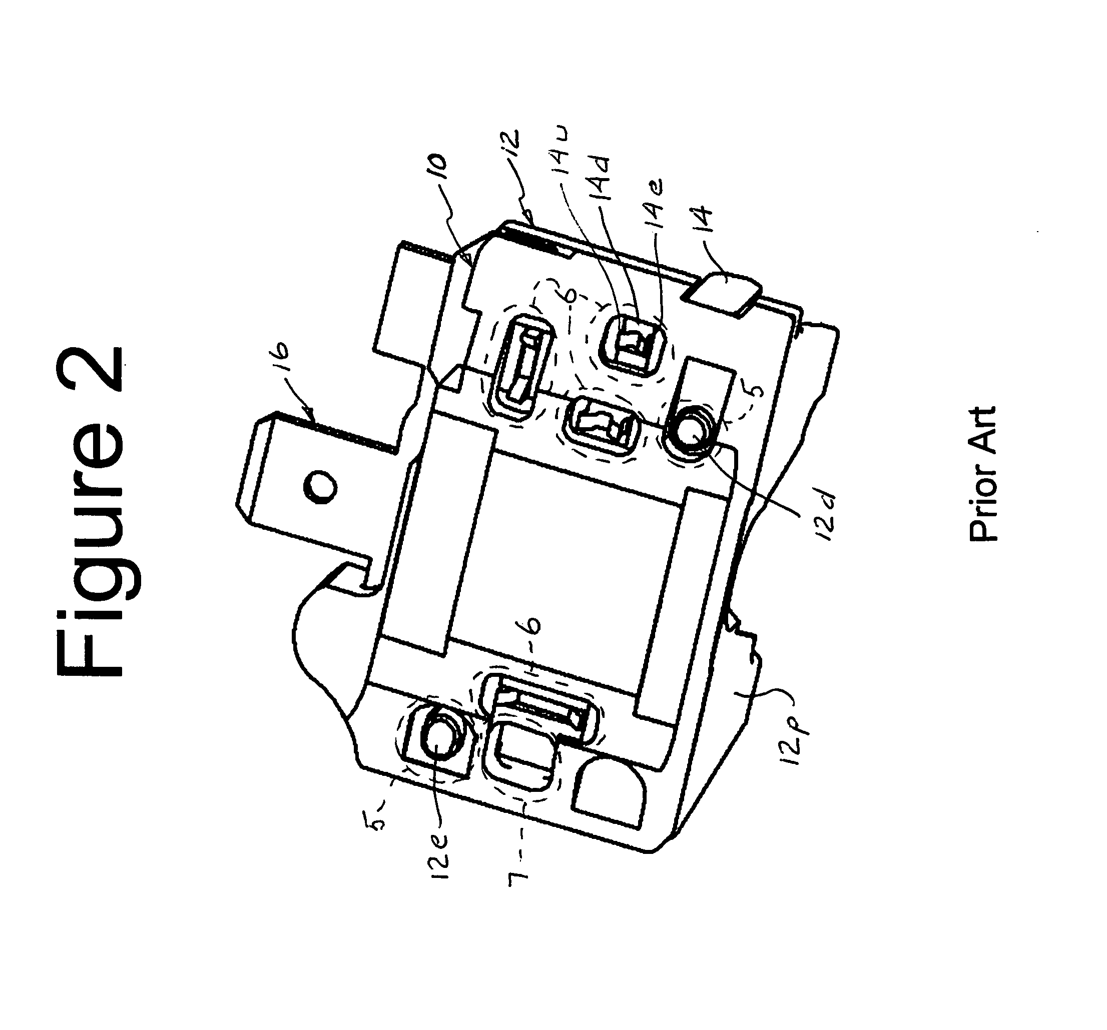
[0026]In the following description references made to top, bottom, side and the like relate to the orientation of the device as shown in FIGS. 3, 5, 8, 9, 13 and 15.

[0027]With reference to FIGS. 1-5, the 4TM and 5TM devices referenced above comprise a housing having a generally rectangular base 10 having a major length along the front of the device and a minor length from front to back of the device. A recess 10a is formed in the base and a cover 12 is received thereon closing the recess. First and second guide pin holes 10t, 10u are formed in the bottom wall for reception of cover guide pins 12d, 12e, respectively, to be discussed. With particular reference to FIG. 3, recess 10a is generally elongated in the direction of the major length having a contact receiving end 10b, an opposite movable contact arm mounting end 10c and a central heater receiving portion 10d intermediate to the two ends. Contact receiving end 10b of the recess is defined by side wall portions 10e on the front,...


PUM


Abstract

An enclosed motor protector has a housing formed by a base (10) and a cover (12) received on the base and enclosing a recess (10a) formed in the base. A first terminal (14) extends through an opening in the housing and mounts a stationary contact (14c) within the recess. An elongated movable contact arm (18) is cantilever mounted at one end in the recess and mounts a second movable contact (18a) on a free end of the arm which is adapted to move into and out of engagement with the stationary contact. A heater (20) is mounted in the recess in heat transfer relation with a snap acting thermostatic disc (22) disposed adjacent to the movable contact arm so that upon reaching a preselected temperature the disc will snap from one dished configuration to an opposite dished configuration with its motion transferred to the movable contact arm to move the contacts out of engagement. The cover is formed with a first multiple wall barrier (122) in the form of a triangular body when seen in a lateral cross section closing a first terminal receiving opening and a second multiple wall barrier (124) closing a second terminal receiving opening to interrupt the travel of arcs and the inlet of explosive gas to the enclosure. These features also diminish air supply in the enclosure to thereby weaken any combustion.

Description

CROSS-REFERENCE TO RELATED APPLICATIONS[0001]Benefit is claimed under 35 U.S.C. Section 119(e) (1) of Provisional Application No. 60 / 618,083, filed Oct. 12, 2004.FIELD OF THE INVENTION[0002]This invention relates generally to motor protectors and more particularly to electrical enclosed break devices.BACKGROUND OF THE INVENTION[0003]U.S. Pat. No. 4,706,152, assigned to Texas Instruments Incorporated, relates to an enclosed break device known as the 4TM and the 5TM. An enclosed break device, according to the International Electrotechnical Commission (IEC) Standard 60079-15 second edition 2001-02, is a “device incorporating electrical contacts that are made and broken and that will withstand an internal explosion of the flammable gas or vapor which may enter it without suffering damage and without communicating the internal explosion to the external flammable gas or vapor.” The 4TM and 5TM devices which have been made in accordance with the referenced patent comply with the first edit...

Claims


Application Information

Patent Timeline
Patent Type & Authority Patents(United States)
IPC IPC(8): H01H37/04H01H37/02
CPCH01H61/002H01H37/5427H01H9/042F25B2400/077H02H7/08
Inventor LIM, ADRIAN W.BRODEUR, RUSSELL P.
Owner SENSATA TECH MASSACHUSETTS INC
Why Eureka
Try Eureka