
Inkjet printing apparatus

a printing apparatus and inkjet technology, applied in printing presses, printing, duplicating/marking methods, etc., can solve the problems of un uniform application of processing liquid to the transfer member, inability to perform satisfactory printing, and damage to one of the transfer member and the liquid collection unit, so as to achieve a higher-quality image

Active Publication Date: 2020-04-07
CANON KK
View PDF22 Cites 0 Cited by
  • Summary
  • Abstract
  • Description
  • Claims
  • Application Information

AI Technical Summary

Benefits of technology

This approach enables higher-quality image printing by maintaining the integrity of the transfer member and ensuring uniform preprocessing liquid application, reducing the risk of damage and improving printing efficiency.

Problems solved by technology

However, unless a contact sequence and a separation sequence of the respective constituent elements with respect to the transfer member are maintained appropriately, the following problem arises, making it impossible to perform satisfactory printing.
Consequently, owing to the preprocessing liquid or the like, a processing liquid is not applied to the transfer member uniformly.
Because the processing liquid is not applied to the transfer member before the liquid collection unit removes a liquid, the transfer member in a dry condition contacts the liquid collection unit, and damage to one of the transfer member and the liquid collection unit is likely to be caused due to friction between them even if a small speed difference occurs between them.
In addition, the liquid collection unit cannot collect a part of the preprocessing liquid, increasing the collection amount of the preprocessing liquid in the cleaning unit in subsequent-processing.
This imposes a large load on a cleaning operation by the cleaning unit.
Because the preprocessing liquid is not applied to the transfer member, a reaction between the preprocessing liquid and ink discharged from a printhead to the transfer member does not occur, making it impossible to form an image appropriately.
The liquid collection unit contacts the transfer member in a dry condition in which the preprocessing liquid is not applied to the transfer member, and damage to one of the transfer member and the liquid collection unit is likely to be caused due to occurrence of friction by the small speed difference between them.

Method used


Image

  • Inkjet printing apparatus
  • Inkjet printing apparatus
  • Inkjet printing apparatus

Examples


Embodiment Construction

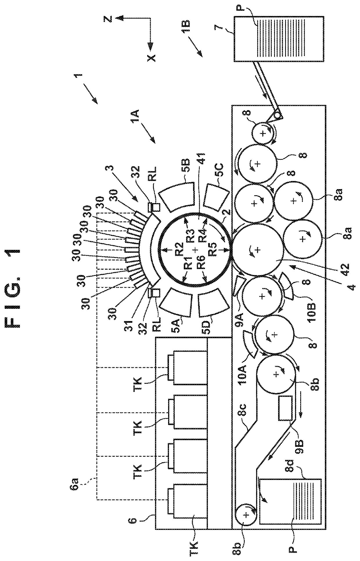
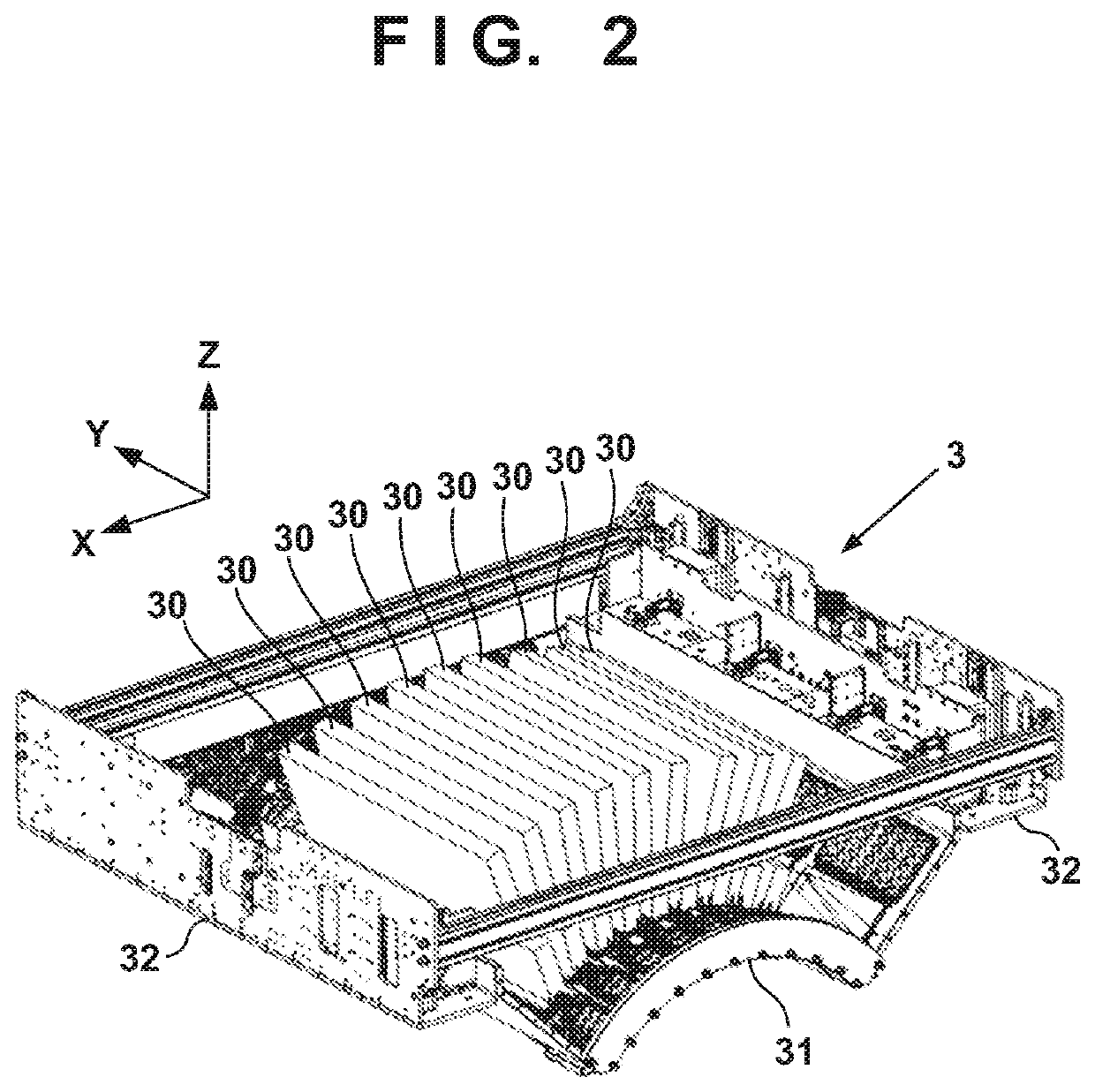
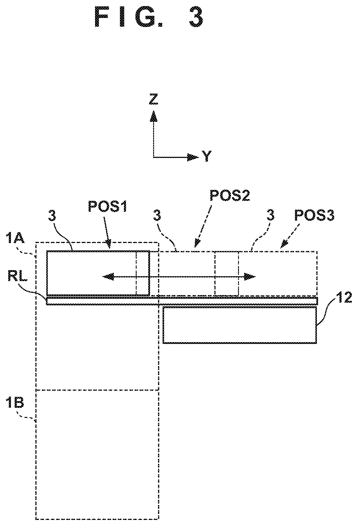
[0039]Exemplary embodiments of the present invention will now be described in detail in accordance with the accompanying drawings. Note that in each drawing, arrows X and Y indicate horizontal directions perpendicular to each other, and an arrow Z indicates a up / down direction.

[0040]

[0041]In this specification, the terms “print” and “printing” not only include the formation of significant information such as characters and graphics, but also broadly includes the formation of images, figures, patterns, and the like on a print medium, or the processing of the medium, regardless of whether they are significant or insignificant and whether they are so visualized as to be visually perceivable by humans.

[0042]Also, the term “print medium (or sheet)” not only includes a paper sheet used in common printing apparatuses, but also broadly includes materials, such as cloth, a plastic film, a metal plate, glass, ceramics, wood, and leather, capable of accepting ink.

[0043]Furthermore, the term “i...


PUM

PropertyMeasurementUnit
pore sizeaaaaaaaaaa
temperatureaaaaaaaaaa

Abstract

A printing apparatus according to an embodiment of this invention brings, out of a cleaning unit that cleans a transfer member in contact with a transfer member and an application unit that applies a reactive liquid with ink to the transfer member, the cleaning unit into contact with the transfer member to clean the transfer member by the cleaning unit at the start of the printing operation. Alternatively, out of the application unit and an absorbing unit that absorbs a liquid component from the reactive liquid applied by the application unit in contact with the transfer member, the printing apparatus brings the application unit into contact with the transfer member to apply the reactive liquid by the application unit.

Description

BACKGROUND OF THE INVENTIONField of the Invention[0001]The present invention relates to an inkjet printing apparatus, and particularly to, for example, an inkjet printing apparatus that transfers an image formed by discharging ink to an intermediate transfer member to a print medium and prints the image.Description of the Related Art[0002]Conventionally, printing apparatuses that perform printing in accordance with an inkjet method includes a printing apparatus configured to discharge ink to an intermediate drum by a printhead, form an image on the intermediate drum, transfer the image to a print medium, and print the image. For example, Japanese Patent Laid-Open No. 2003-182064 discloses an arrangement that includes an image forming unit using an inkjet printhead (to be referred to as a printhead hereinafter), a liquid collection unit, a transfer processing unit, and the like around an intermediate transfer member (also simply referred to as a transfer member) such as the intermedi...

Claims


Application Information

Patent Timeline
Patent Type & Authority Patents(United States)
IPC IPC(8): B41J2/01B41J2/005
CPCB41J2/0057B41J2002/012B41F19/007B41F35/00B41P2235/21B41P2235/20B41J2/14B41M5/50B41J29/17B41J2002/14362B41J2202/14
Inventor TAKEUCHI, TOSHIKISUGIMOTO, MASAHIROTSUSHIMA, IPPEIFUKUI, KOHEIIZUMI, MASATOSATO, RYOSUKESUGIYAMA, KENJINIEDA, KENGOUCHIDA, KOTAYANAGI, YUICHIRONAKAYA, YUSUKESAKAMOTO, ATSUSHIHIROSAWA, SUSUMUMURASE, TAKESHIHIROSE, FUTOSHI
Owner CANON KK
Learn More