Solid-state image capture element, driving method, and electronic device

a technology of solid-state image and capture element, which is applied in the direction of color television, television system, radio control device, etc., can solve the problem that the configuration suitable for capturing a moving image in which the potential of the overflow gate is low, and is not suitable for capturing a still image, etc., to achieve the effect of high-quality imag

Active Publication Date: 2019-07-16
SONY CORP
View PDF10 Cites 0 Cited by
  • Summary
  • Abstract
  • Description
  • Claims
  • Application Information

AI Technical Summary

Benefits of technology

[0017]According to an aspect of the present disclosure, a higher-quality image can be captured.

Problems solved by technology

Therefore, a configuration suitable for capturing a moving image in which the potential of the overflow gate is formed low is not suitable for capturing a still image.

Method used


Image

  • Solid-state image capture element, driving method, and electronic device
  • Solid-state image capture element, driving method, and electronic device
  • Solid-state image capture element, driving method, and electronic device

Examples


Embodiment Construction

[0041]Hereinbelow, a specific description is given of specific embodiments to which the present technology is applied with reference to the drawings.

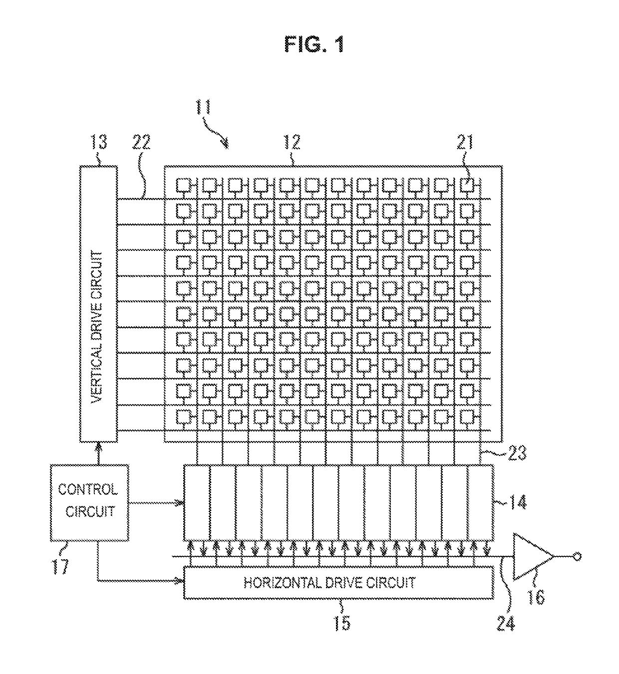
[0042]FIG. 1 is a block diagram showing a configuration example of an embodiment of an image capture element to which the present technology is applied.

[0043]As shown in FIG. 1, an image capture element 11 includes a pixel region 12, a vertical drive circuit 13, a column signal processing circuit 14, a horizontal drive circuit 15, an output circuit 16, and a control circuit 17.

[0044]The pixel region 12 is a light receiving surface that receives light collected by an optical system (not shown). In the pixel region 12, a plurality of pixels 21 is arranged in a matrix, and each pixel 21 is connected to the vertical drive circuit 13 via a horizontal signal line 22 for each row and to the column signal processing circuit 14 via a vertical signal line 23 for each column. The plurality of pixels 21 outputs pixel signals at levels in accordance...


PUM


Abstract

The present disclosure relates to a solid-state image capture element in which, at least two or more of the discharge driving units are arranged in series between the photoelectric conversion unit and the discharge unit. During capturing of a still image, when a reset operation of the photoelectric conversion unit is performed in starting exposure of the pixel, driving is performed such that after potentials of all the discharge driving units arranged in series are reduced and the charge remaining in the photoelectric conversion unit is discharged to the discharge unit, the potential of the discharge driving unit on the photoelectric conversion unit side is returned to an original potential first, and then the potential of another discharge driving unit is returned to an original potential. The present technology can be applied to a CMOS image sensor which performs imaging by, for example, a global shutter method.

Description

CROSS REFERENCE TO RELATED APPLICATIONS[0001]This application is a U.S. National Phase of International Patent Application No. PCT / JP2016 / 058648 filed on Mar. 18, 2016, which claims priority benefit of Japanese Patent Application No. JP 2015-076686 filed in the Japan Patent Office on Apr. 3, 2015. Each of the above-referenced applications is hereby incorporated herein by reference in its entirety.TECHNICAL FIELD[0002]The present disclosure relates to a solid-state image capture element, a driving method, and an electronic device, and particularly, relates to a solid-state image capture element, a driving method, and an electronic device which are enabled to capture a high-quality image.BACKGROUND ART[0003]Conventionally, in an electronic device with an imaging function, such as a digital still camera or a digital video camera, for example, a solid-state image capture element, such as a charge coupled device (CCD) or a complementary metal oxide semiconductor (CMOS) image sensor is us...

Claims


Application Information

Patent Timeline
Patent Type & Authority Patents(United States)
IPC IPC(8): H04N5/363H04N5/3745H04N5/359H01L27/146H04N5/357
CPCH04N5/363H01L27/14614H01L27/14641H01L27/14643H04N5/37452H04N5/3575H04N5/3592H04N5/3597H01L27/14656H01L27/14603H04N25/623H04N25/616H04N25/622H04N25/626H04N25/771H04N25/77H04N25/65
Inventor KUMAGAI, YOSHIMICHI
Owner SONY CORP
Why Eureka
Try Eureka