Image processing apparatus and image processing method

a technology of image processing and image processing, applied in the field of image processing apparatus and image processing method, can solve the problems of image degradation, large psfs and large calculation amount, and difficulty in psf data exchange between the lens and the camera, so as to reduce blur

Inactive Publication Date: 2014-02-11
CANON KK
View PDF11 Cites 0 Cited by
  • Summary
  • Abstract
  • Description
  • Claims
  • Application Information

AI Technical Summary

Benefits of technology

[0009]The present invention has been made in consideration of the above problems, and provides a technique of generating a higher-quality image, by performing image processing to reduce blurs resulted from lens aberrations using data whose data amount is smaller.

Problems solved by technology

Image degradation is known to occur when an object image captured by an image input apparatus such as a digital camera blurs more than actual due to the influence of aberrations of the lens and the like.
In the related art, however, the enormous data amount of PSFs and the large calculation amount pose a problem.
In this case, the data amount of the PSFs becomes enormous, resulting in difficulty in PSF data exchange between the lens and the camera.
When a PSF is held for each concentric region, as in patent reference 2, the region boundaries pose a problem.
On the other hand, when holding the PSFs and calculating recovery filters from the PSFs at the time of image capturing, as in patent references 1 and 2, processing such as Fourier transformation in high calculation cost is necessary, resulting in a large calculation amount.

Method used


Image

  • Image processing apparatus and image processing method
  • Image processing apparatus and image processing method
  • Image processing apparatus and image processing method

Examples


first embodiment

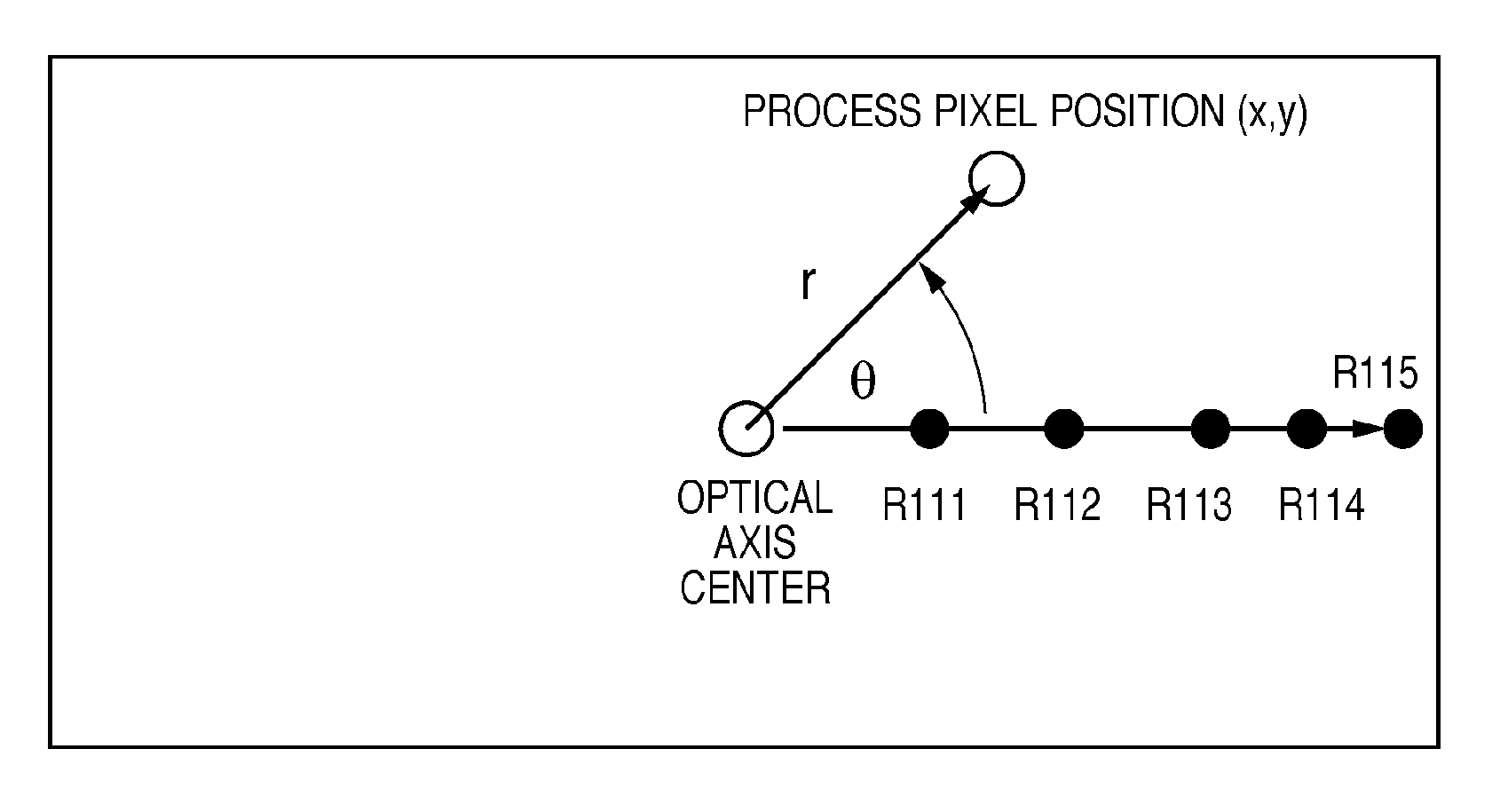
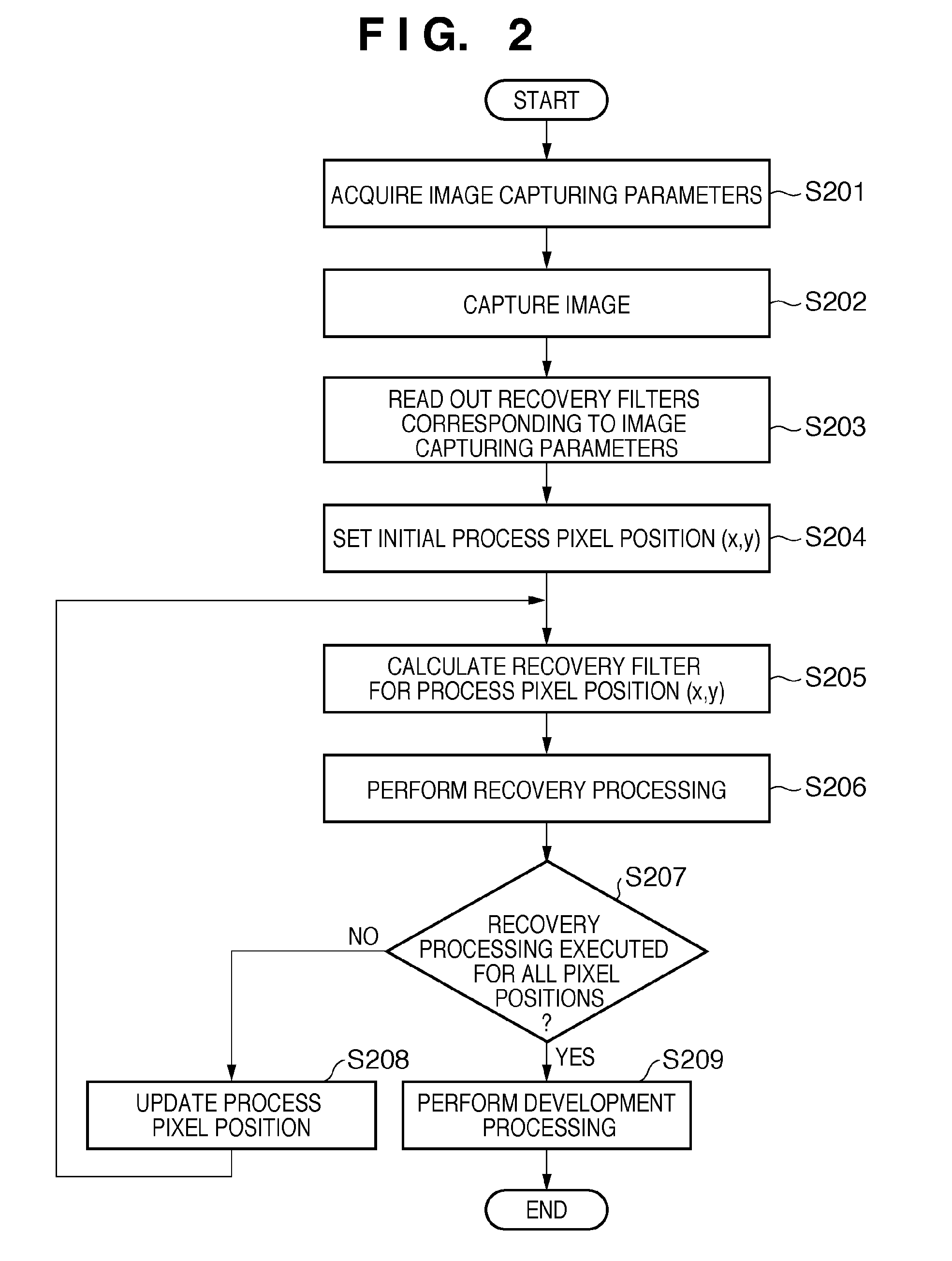
[0029]Using the symmetry of blur recovery filters to be used to reduce blurs caused by lens aberrations, an image capturing apparatus according to this embodiment holds blur recovery filters for only one image height direction in the memory (lens memory) of the lens unit detachable from the camera body. When performing processing (blur recovery processing) of reducing blurs caused by lens aberrations on the camera body side, a blur recovery filter is acquired from the lens unit, expanded, and applied to the image. This enables to perform processing of reducing blurs caused by lens aberrations for an entire image.

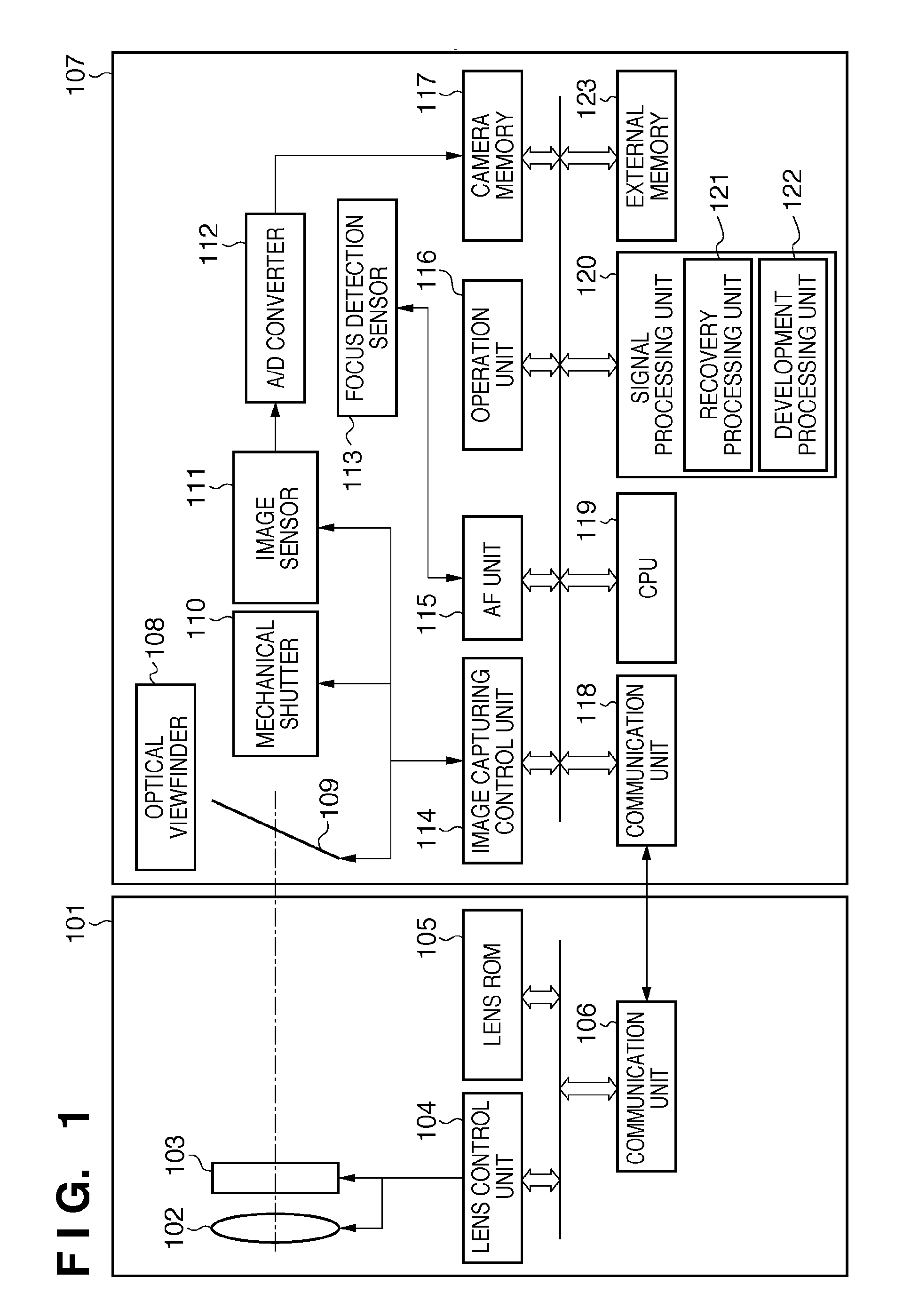
[0030]The image capturing apparatus according to the embodiment will be described with reference to the block diagram of FIG. 1. As shown in FIG. 1, the image capturing apparatus according to the embodiment includes a camera body 107 and a lens unit 101 that is detachable from the camera body 107 and communicable with it.

[0031]First, the lens unit 101 will be explained. Ligh...

second embodiment

[0061]In the first embodiment, the lens unit 101 is a device separated from the camera body 107. However, an image capturing apparatus in which the lens unit 101 is integrated with the camera body 107 can also be considered. FIG. 8 shows an example of the arrangement of an image capturing apparatus in which a lens unit 101 is integrated with a camera body 107. In this case, blur recovery filters corresponding to the respective image heights for image capturing parameters are stored in a camera memory 117, although they are stored in the lens ROM 105 in the above-described embodiment. Note that the second embodiment is the same as the first embodiment except this point.

third embodiment

[0062]In the first and second embodiments, a case has been described in which image quality recovery processing is implemented by the image capturing apparatus. However, the image quality recovery processing can be implemented by any apparatus other than the image capturing apparatus if it can acquire and process an image. In this embodiment, an example will be described in which application software for implementing the image quality recovery processing is installed in an image processing apparatus such as a PC (Personal Computer) so that the image processing apparatus implements the above-described image quality recovery processing by executing the application.

[0063]An example of the functional arrangement of the image processing apparatus according to this embodiment will be described first with reference to the block diagram of FIG. 9. A recovery filter DB (database) 902 is connected to an image processing apparatus 901 via a network 903. The image processing apparatus 901 commu...


PUM


Abstract

A recovery processing unit performs an image quality recovery processing of reducing a blur in an image using a filter to reduce a blur at an image height position for each image height on a line from the center position of the image to an end of the image.

Description

BACKGROUND OF THE INVENTION[0001]1. Field of the Invention[0002]The present invention relates to a technique of generating a higher-quality image by performing image processing to reduce blurs resulted from lens aberrations.[0003]2. Description of the Related Art[0004]Image degradation is known to occur when an object image captured by an image input apparatus such as a digital camera blurs more than actual due to the influence of aberrations of the lens and the like. A technique using the PSFs (Point Spread Functions) of an optical system is known as a technique of recovering the image quality by image processing (patent reference 1 (Japanese Patent Laid-Open No. 2001-197354) and patent reference 2 (Japanese Patent No. 03532368)). The technique using PSFs obtains a function (recovery function) for recovery based on a PSF and performs recovery processing using the recovery function. In this recovery processing, the PSF varies in accordance with the conditions of the lens type, the a...

Claims


Application Information

Patent Timeline
Patent Type & Authority Patents(United States)
IPC IPC(8): H04N5/228G06K9/40H04N5/217H04N5/225
CPCH04N5/3572H04N25/61
Inventor SEKINE, HISATO
Owner CANON KK
Why Eureka
Try Eureka