Power converter and control method thereof

a power converter and control method technology, applied in the direction of electric variable regulation, process and machine control, instruments, etc., can solve the problems of increasing the power consumption of the bus bar, increasing the square current of the low voltage bus bar, and increasing the current with the square current. achieve the effect of optimizing the converting efficiency of the power converter

Active Publication Date: 2020-04-07
DELTA ELECTRONICS (SHANGHAI) CO LTD
View PDF23 Cites 0 Cited by
  • Summary
  • Abstract
  • Description
  • Claims
  • Application Information

AI Technical Summary

Benefits of technology

[0012]In accordance with an aspect of the present disclosure, there is provided a method of controlling a power converter having a first stage converter and a second stage converter. The method includes the following steps. Firstly, an input voltage is converted into an intermediate voltage. Then, the intermediate voltage is converted into an output voltage and the output voltage is provided to a load. Thereafter, a loading amount of the load is detected. If the loading amount of the load is larger than a first threshold value, the intermediate voltage is adjusted to increase a voltage difference between the intermediate voltage and the output voltage, so that a change of the intermediate voltage is negatively correlated with a change of the loading amount of the load. If the loading amount of the load is smaller than a second threshold value, keep the intermediate voltage unchanged or adjust the intermediate voltage, so that the change of the intermediate voltage is positively correlated with the change of the loading amount of the load within at least a loading change range. The first threshold value is larger than the second threshold value.
[0006]Generally, the power supply voltage of the processor or the large-scale integrated circuit is low. Consequently, if the voltage difference between the power supply voltage of the processor or the large-scale integrated circuit and the received bus voltage of the power converter is higher, the converting efficiency is lower. In case that the bus voltage is high, the converting efficiency of the two-stage power converter is superior to the converting efficiency of the single-stage power converter.

Problems solved by technology

However, since the processing capability for the processors or large-scale integrated circuits increase, the power consumption also increases.
As the power consumption of the processors or large-scale integrated circuits increase, the current withstood by the low voltage bus bar gradually increases.
Without decreasing the wiring impedance of the bus bar, the power consumption of the bus bar increases with the square of the current.
Consequently, the conventional method of powering the server system or the communication system wastes energy and generates a great deal of heat.
The generation of heat decreases stability and reliability of the server system or the communication system.
However, since the output voltage Vout is the only parameter to be controlled, the converting efficiency of the second stage converter 11 is not surely optimized in all possible load conditions (e.g., a light load condition or a heavy load condition) while achieving the output feature.
That is, the converting efficiency of the first stage converter 10 is not surely optimized in all possible load conditions.

Method used


Image

  • Power converter and control method thereof
  • Power converter and control method thereof
  • Power converter and control method thereof

Examples


first embodiment

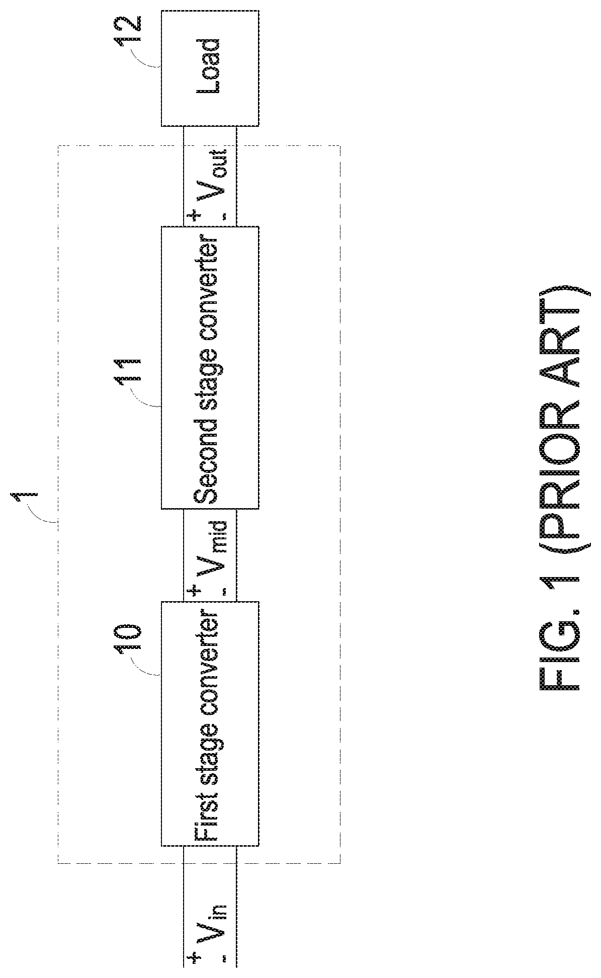
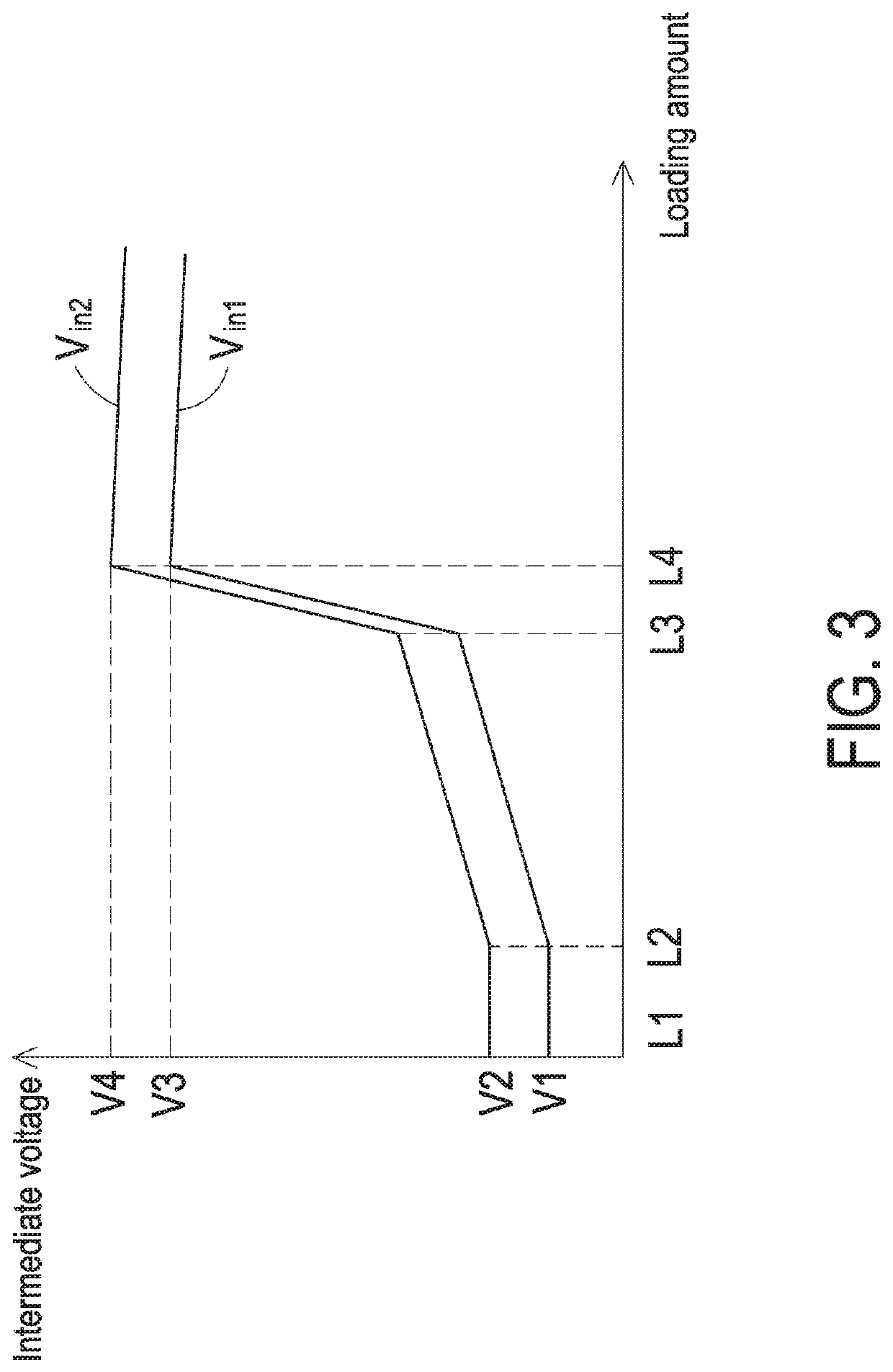
[0038]FIG. 3 schematically illustrates the relationship between the received intermediate voltage of the second stage converter of the power converter and the loading amount of the load by a control method according to the present disclosure. In FIG. 3, the horizontal axis indicates the change of the loading amount of the load 12, and the vertical axis indicates the magnitude of the intermediate voltage Vmid. The curves Vin1 and Vin2 indicate the input voltages received by the first stage converter 10 in different conditions. The control method of the present disclosure includes the following steps. Firstly, the loading amount of the load 12 is detected. If the loading amount L4 of the load 12 is larger than a first threshold value, the load 12 is in a heavy load condition. In the heavy load condition, the intermediate voltage Vmid from the first stage converter 10 is adjusted to increase the voltage difference between the intermediate voltage Vmid and the output voltage Vout. Conse...

second embodiment

[0046]FIG. 5 schematically illustrates the relationship between the received intermediate voltage of the second stage converter of the power converter and the loading amount of the load by a control method according to the present disclosure. Please refer to FIG. 5. If the load 12 is in the light load condition and the loading amount of the load 12 is decreased to loading amount L2, which is smaller than the third threshold value, the intermediate voltage Vmid is increased with the decreasing loading amount of the load 12 (see FIG. 5). That is, the change of the intermediate voltage Vmid and the change of the loading amount of the load 12 are in a negative linear correlation with a slope in a range between −1 and 0. Regardless of the change of the intermediate voltage Vmid, when the load 12 is in the light load condition and the loading amount of the load 12 is smaller than the third threshold value, the intermediate voltage Vmid is at least 1.1 times the output voltage Vout. Conseq...

third embodiment

[0047]FIG. 6 schematically illustrates the relationship between the received intermediate voltage of the second stage converter of the power converter and the loading amount of the load by a control method according to the present disclosure. Please refer to FIG. 6. If the load 12 is in the light load condition and the loading amount of the load 12 is decreased to loading amount L2, which is smaller than the third threshold value, the intermediate voltage Vmid is maintained at a fixed value (e.g., the voltage V1 as shown in FIG. 6). That is, regardless of whether the received input voltage of the first stage converter 10 is Vin1, Vin2 or another value, the intermediate voltage Vmid is maintained at V1. In other words, if the load 12 is in the light load condition and the loading amount of the load 12 is smaller than the third threshold value, the intermediate voltage Vmid is maintained at the fixed value and is not related to the received input voltage of the first stage converter 1...


PUM


Abstract

A control method of a power converter including a first stage converter and a second stage converter is provided. The first stage converter converts an input voltage into an intermediate voltage. The second stage converter converts the intermediate voltage into an output voltage to power a load. If a loading amount of the load is larger than a first threshold value, the intermediate voltage is adjusted to increase a voltage difference between the intermediate voltage and the output voltage, so that a change of the intermediate voltage is in a negative correlation with a change of the loading amount. If the loading amount is smaller than a second threshold value, the intermediate voltage remains be unchanged or the intermediate voltage is adjusted, so that the change of the intermediate voltage is in positive correlation with the change of the loading amount.

Description

CROSS-REFERENCE TO RELATED APPLICATION[0001]This application claims priority to China Patent Application No. 201610247799.3, filed on Apr. 20, 2016, the entire contents of which are incorporated herein by reference for all purposes.FIELD OF THE DISCLOSURE[0002]The present disclosure relates to a power converter and a control method thereof, and more particularly to a two-stage power converter and a control method thereof.BACKGROUND OF THE DISCLOSURE[0003]With increasing development of internet and communication technologies, the living styles of people are deeply changed. As the internet and communication technologies become more powerful, more powerful processors or large-scale integrated circuits are required to process data. However, since the processing capability for the processors or large-scale integrated circuits increase, the power consumption also increases. Therefore, it is important to increase the converting efficiency of the power converters of the processors or large-...

Claims


Application Information

Patent Timeline
Patent Type & Authority Patents(United States)
IPC IPC(8): H02M3/337H02M1/00
CPCH02M3/3374H02M2001/007H02M3/156H02M1/0019H02M1/007H02M3/1566H02M3/1584H02J1/102Y02B70/10H02M1/0035H02M1/0032
Inventor ZHANG, YUYE, HAOYIZENG, JIANHONG
Owner DELTA ELECTRONICS (SHANGHAI) CO LTD
Why Eureka
Try Eureka