Chuck

a drilling tool and chuck technology, applied in the direction of chucks, manufacturing tools, mechanical equipment, etc., can solve the problems of reducing the flexibility of the user's operation, wasting both time and labor, and difficult to align the tool bit, so as to achieve precise and reliable alignment, stable pre-tightening force, and convenient and safe operation

Active Publication Date: 2020-04-28
POSITEC POWER TOOLS (SUZHOU) CO LTD
View PDF19 Cites 1 Cited by
  • Summary
  • Abstract
  • Description
  • Claims
  • Application Information

AI Technical Summary

Benefits of technology

[0034]Since the above technical solution is adopted, the present invention overcomes the defects of an instable pre-tightening action, a poor aligning effect and unsafe operation of the aligning and pre-tightening structures of the drill chucks in the prior art, such that the tool bit does not need to additional manual holding operation during the chuck mode, and therefore, the operation is more convenient and safe. Besides, the aligning effect is precise and reliable, and the pre-tightening force is stable.

Problems solved by technology

However, in actual operation, in order to ensure that the tool bit is in the center of a clamping part, an operator often has to hold the tool bit with hand or other holding tool till the clamping jaws applies a certain action force to the tool bit, which is very inconvenient.
Besides, in a bad working condition, the operation flexibility of the user is reduced, it is hard to align the tool bit with the clamping part of the drill chuck rapidly and then the operator has to repeat the operation again and again, and both time and labor are wasted.
During a chuck mode of an auto chuck in which a motor drive the chuck body to rotate relative to the sleeve, the tool bit is easily impacted to be directly thrown out to injure the operator who holds tool bit.

Method used


Image

  • Chuck
  • Chuck
  • Chuck

Examples


first embodiment

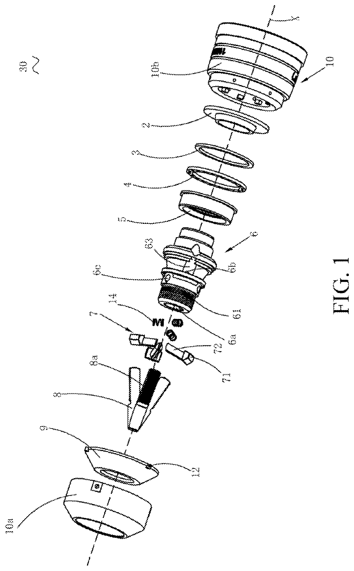
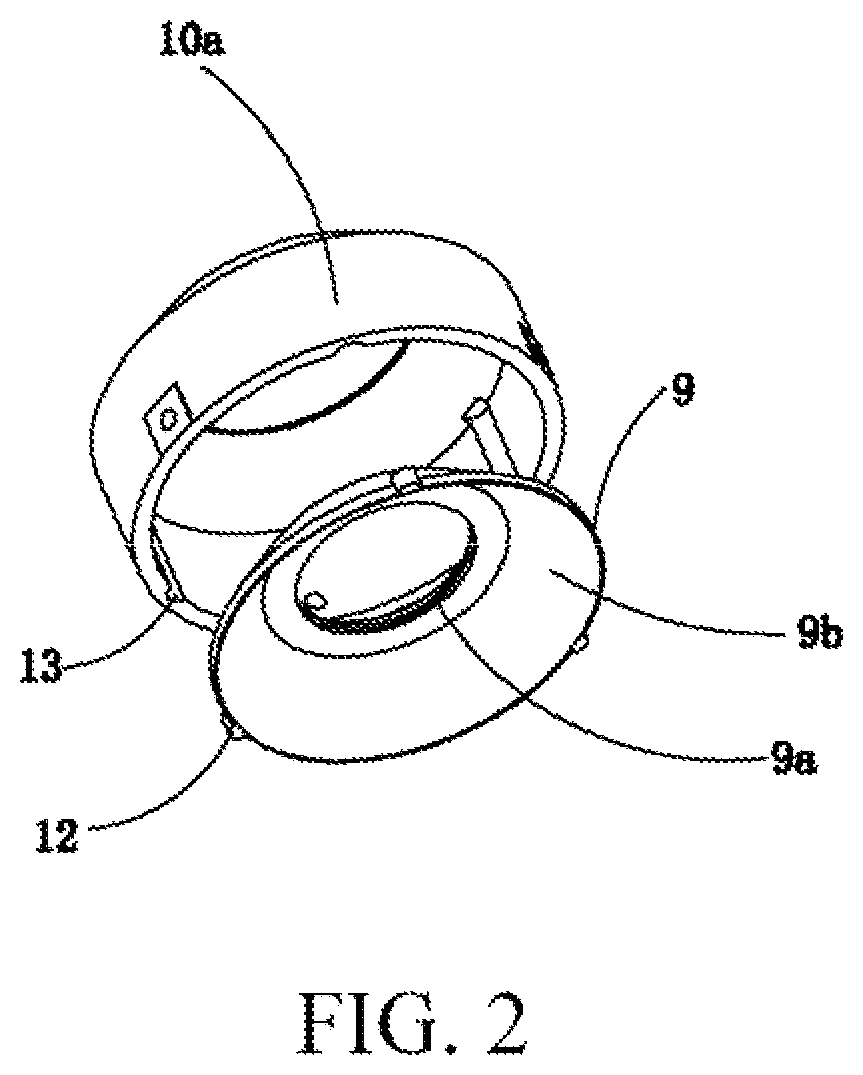
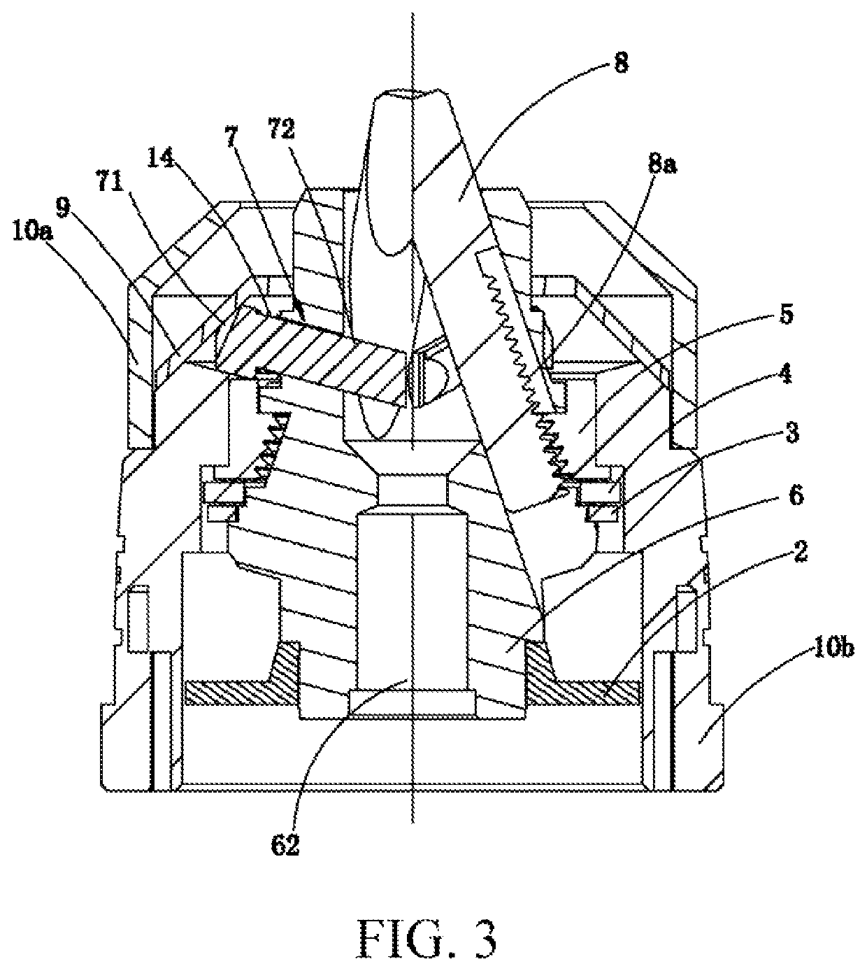
[0055]Referring to FIGS. 1 to 4, the embodiment provides a chuck 30, the chuck 30 has a sleeve 10, the sleeve 10 comprises a front sleeve 10a and a rear sleeve 10b coupled to the front sleeve 10a. The chuck body 6 having a longitudinal axis X is disposed within the sleeve 10 rotatable relative to the sleeve 10. A first shaft cavity 6a for mounting a tool bit is disposed on the front end of chuck body 6, and a central line of the first shaft cavity 6a and the longitudinal axis of the chuck body 6 are disposed coaxially. A plurality of first guide holes 6b communicated in the first shaft cavity 6a distribute around the first shaft cavity 6a with uniformity. And the first guide holes 6b are configured in the side wall of the chuck body 6. In the present embodiment, the number of the first guide holes 6b is three (FIG. 1 only shows one guide hole), but not limited to three. Each of the first guide holes 6b is configured to allow the jaw 8 to stretch and penetrate. One end of the each ja...

second embodiment

[0077]FIG. 7 is a sectional view of a chuck provided in a second embodiment of the present invention. FIG. 8 is a top view of a locating member as shown in FIG. 7. The present embodiment is an alternate embodiment of the first embodiment, and provides a chuck, and such chuck differs from the first embodiment in:

[0078]As shown in FIG. 7, the locating member in the present embodiment is a magnetic locating member 7a, and compared with the of the elastic locating member 7s of the first embodiment, there is only one magnetic locating member 7a, which is disposed opposite to one of the clawing claws 8, in this way, the chuck jaws 8 and the magnetic locating member 7a can abut against the tool bit toward two directions, the aligning effect is more precise, the magnetic locating member 7a comprises a holding part 74 and a magnet 11 disposed on the end part of the holding part 74 extending to the first shaft cavity for adsorbing the tool bit 15, since the tool bit 15 is mostly made of a met...

third embodiment

[0081]FIG. 9 is a sectional view of a chuck provided in a third embodiment of the present invention. FIG. 10 is a top view of a locating member as shown in FIG. 9. The present embodiment is an alternate embodiment of the first embodiment, and provides a chuck, and such chuck differs from the first embodiment in:

[0082]In the present embodiment, the locating members and the chuck jaws 8 are disposed oppositely, the amount of the locating members is consistent with that of the chuck jaws 8, the locating member comprises a magnetic locating member 7a and a nonmagnetic locating member 7b, wherein the magnetic locating member 7a comprises a holding part 74 and a magnet 11 disposed on the end part of the holding part 74 extending into the first shaft cavity for adsorbing the tool bit 15, and the nonmagnetic locating member 7b comprises a holding part.

[0083]As shown in FIG. 10, in the present embodiment, the amount of the chuck jaws 8 and the amount of the locating members are three prefera...


PUM


Abstract

The invention relates to a chuck having a sleeve, a chuck body, a plurality of chuck jaws, an adjusting mechanism configured to adjust relative movement between the chuck jaws and the chuck body, at least one locating member and a pushing mechanism. The locating member is disposed on the chuck body between the adjacent chuck jaws. When the adjusting mechanism drives the chuck jaws to approach to each other relative to the longitudinal axis, the pushing mechanism pushes the locating member to move towards the longitudinal axis. When the adjusting mechanism drives the chuck jaws to move away from each other relative to the longitudinal axis, the pushing mechanism pushes the locating member to move away from the longitudinal axis. Therefore, the operation is more convenient and safer; the aligning effect is precise and reliable, and the pre-tightening force is stable.

Description

BACKGROUND OF THE INVENTION[0001]The present invention relates to the clamps of drilling tool for machining, and in particular to a tool chuck.[0002]When the tools such as a machine tool and an electric drill are used for the operation of drilling, milling and the like, a tool chuck is often used to clamp and locate a tool bit to improve the accuracy of drilling or milling. The tool chuck is usually comprising a chuck body, a plurality of jaws, a sleeve and a screw nut fixedly connected to the sleeve, the jaws are disposed in an inclined hole designed in the chuck body, and the jaws are driven to moves towards and away from the axis of the chuck body via the relative rotation between the chuck body and the sleeve, thereby realizing the clamping and releasing of the tool bit. However, in actual operation, in order to ensure that the tool bit is in the center of a clamping part, an operator often has to hold the tool bit with hand or other holding tool till the clamping jaws applies a...

Claims


Application Information

Patent Timeline
Patent Type & Authority Patents(United States)
IPC IPC(8): B23B31/12B23B31/28
CPCB23B31/12B23B31/28B23B31/1238B23B2231/44B23B2231/52Y10T279/26
Inventor XIE, MINGJIANWANG, FEIRUN, SHANGLIANG
Owner POSITEC POWER TOOLS (SUZHOU) CO LTD
Why Eureka
Try Eureka