Wire electrical discharge machine
a wire electrical discharge machine and wire technology, applied in the direction of electrical circuits, electrical-based machining electrodes, manufacturing tools, etc., can solve the problems of increasing cost, greatly affecting the peak value of suppressible machining current, etc., and achieves a wide range of voltage and suppresses the flow of machining curren
- Summary
- Abstract
- Description
- Claims
- Application Information
AI Technical Summary
Benefits of technology
Problems solved by technology
Method used
Image
Examples
first embodiment
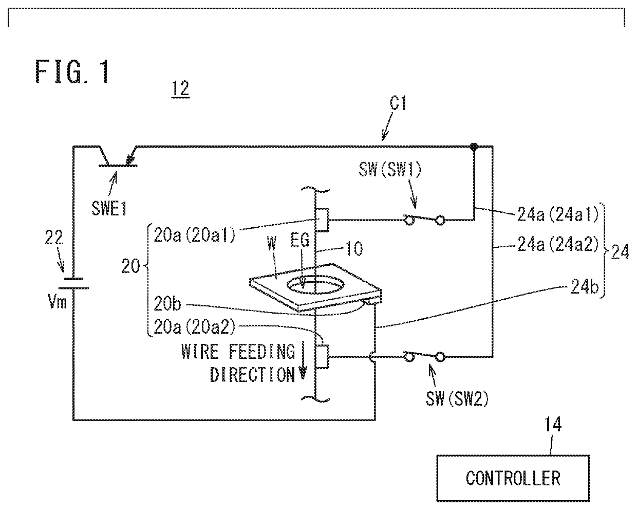
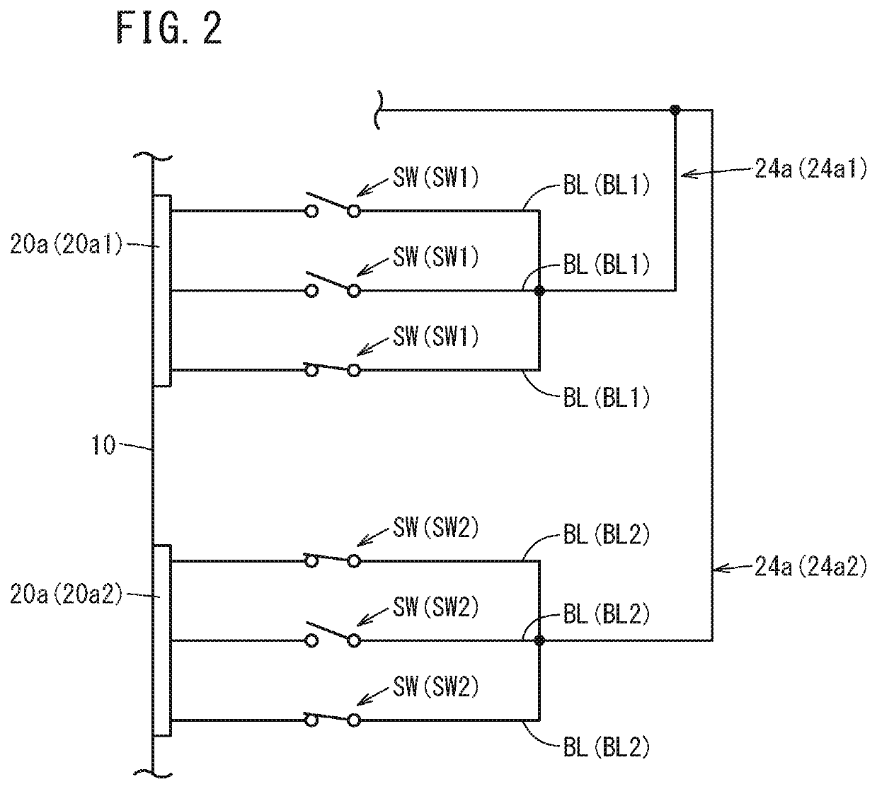
[0016]FIG. 1 is a diagram showing a configuration example of a wire electrical discharge machine 12 according to a first embodiment of the present invention. The wire electrical discharge machine 12 performs electrical discharge machining by applying voltage across an electrode gap EG formed between a wire electrode 10 and an object to be machined (workpiece) W to flow a machining current (discharge current). The wire electrical discharge machine 12 machines the workpiece W by feeding the wire electrode 10 in the Z-direction toward the workpiece W while changing the relative position between the wire electrode 10 and the workpiece W on the XY-plane orthogonal to the Z-direction. That is, the wire electrode 10 is relatively moved along a predetermined path on the workpiece W to thereby machine the workpiece W. A core is formed during this cutting process. The wire electrical discharge machine 12 has a core retaining function for fixing the core that was formed during machining, to th...
second embodiment
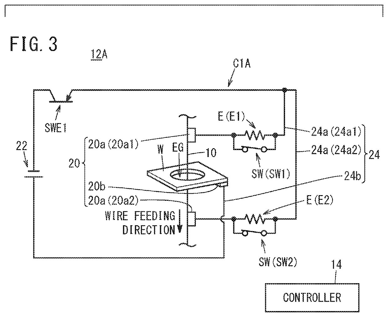
[0030]FIG. 3 is a diagram showing a configuration example of a wire electrical discharge machine 12A according to a second embodiment of the present invention. In the second embodiment, the same components as those described in the first embodiment are allotted with the same reference numerals and only different parts will be described below.
[0031]The machining circuit, designated by C1A, of the wire electrical discharge machine 12A of the second embodiment is the same as the machining circuit C1 described in the first embodiment except that a current suppression element E is disposed on each of the first current supply lines 24a and the switch SW is provided for the first current supply line 24a so as to be connected in parallel with the current suppression element E. The current suppression element E disposed on the first current supply line 24a1 is denoted as E1 and the current suppression element E disposed on the first current supply line 24a2 is denoted as E2. Therefore, the s...
modification 1
[0037]FIG. 5 is a diagram showing a configuration example of a wire electrical discharge machine 12B in Modification 1. In the following description, Modification 1 is applied to the machining circuit C1 (FIG. 1) described in the first embodiment, but it can also be applied to the machining circuit C1A (FIG. 3) described in the second embodiment.
[0038]In addition to the machining circuit C1 and the controller 14, the wire electrical discharge machine 12B of Modification 1 further includes a circuit (hereinafter, referred to as a discharge inducing circuit) C2 for applying a voltage (an inducing voltage) Vs to the electrode gap EG to induce electric discharge. The discharge inducing circuit C2 includes a power source (hereinafter referred to as a discharge inducing power source) 30 and a switching element SWE2 composed of an FET or the like.
[0039]The discharge inducing power source 30 includes a DC power supply. In Modification 1, in order to apply a positive polarity voltage Vs to t...
PUM
| Property | Measurement | Unit |
|---|---|---|
| current | aaaaa | aaaaa |
| current | aaaaa | aaaaa |
| impedance | aaaaa | aaaaa |
Abstract
Description
Claims
Application Information
 - R&D
- Intellectual Property
- Life Sciences
- Materials
- Tech Scout
- Unparalleled Data Quality
- Higher Quality Content
- 60% Fewer Hallucinations
Browse by: Latest US Patents, China's latest patents, Technical Efficacy Thesaurus, Application Domain, Technology Topic, Popular Technical Reports.
© 2025 PatSnap. All rights reserved.Legal|Privacy policy|Modern Slavery Act Transparency Statement|Sitemap|About US| Contact US: help@patsnap.com


