Supercharge Your Innovation With Domain-Expert AI Agents!

Progressive damping system for a track system

a technology of progressive damping and track system, which is applied in the direction of vibration dampers, resilient suspensions, vehicle springs, etc., can solve the problems of affecting the adaptation of suspension elements, the oscillation of load with regard to the track system, and the existing track system does not benefit from the damping provided, so as to maximize the road comfort and minimize the effect of vibration

Active Publication Date: 2020-05-05
SOUCY INT
View PDF85 Cites 0 Cited by
  • Summary
  • Abstract
  • Description
  • Claims
  • Application Information

AI Technical Summary

Benefits of technology

[0008]The shortcomings of the prior art are generally mitigated by the track assembly herein described that maximizes road comfort. The track assembly comprises a sprocket, an optional final drive, an optional one piece main frame, an optional front split frame, an optional rear split frame, at least one secondary pivoting assembly, at least one idler wheel, a plurality of sets of support wheels, at least one shock absorber, a spring, such as but not limited to mechanical, pneumatic or hydraulic springs, a track band, frame components, etc. The track assembly comprising these components is assembled in particular configurations for the track assembly as a whole to minimize the vibration that are communicated through the assembly to the vehicle and accordingly to the vehicle operator.
[0009]One aspect of the present invention is to maintain a constant level of comfort and performance as the load of the agriculture machinery varies during normal working conditions.
[0011]This invention allows using a complete passive system on a track vehicle and having a near optimum damping value, without any intervention of the vehicle operator or electric automate or any connection between vehicle and track system to adjust the damping value. This can also works with semi-active and active suspension system. Only the stroke position adjusts the damping value. The damping value change could be made, for example, by adding progressive groove opening onto cylinder surface to restrict / unrestrict hydraulic flow.
[0014]In another aspect of the invention, the track system as described herein above further comprises a damping system being fluid-based, the damping system comprising a reservoir fluidly connected to a damping element, the damping system being configured to vary the flow of fluid between the damping element and the reservoir as a function of the load applied on the damping element. The damping element comprises a hollow portion having a closed end and being fluidly connected to the reservoir; a piston, the piston being adapted to slidingly move inside the hollow portion. As the piston slidingly moves inside the hollow piece toward the closed end, fluid is pushed from the hollow piece to the reservoir, and flow of fluid circulating between the hollow piece and the reservoir is reduced thereby increasing a damping force.
[0018]The control signal may allow the active fluid flow control mean to block or limit the flow of fluid between the hollow portion and the reservoir.
[0020]The invention is further directed to a method for varying the damping value of a damping system of a track system, the method comprising varying the flow of a fluid between a hollow portion of a suspension element and a reservoir in relation to movement of a piston within the hollow portion to provide a damping value dynamically varying as a function of load applied on the track system.

Problems solved by technology

Traction and flotation have always been important issues with farming and construction vehicles.
One of the challenges of track systems is to provide a smooth ride to the operator without regard to the parameters of the vehicle, such as the load.
One of the drawbacks of existing track systems is the comfort.
One of the reasons is that existing track systems do not benefit from the damping provided by the layer of air within the tires.
Another drawbacks of the existing track systems is the adaptation of the suspension elements to the variation of load or of charge of the vehicle.
Indeed, when load or charge is increased on the vehicle, the oscillation of the load with regard to the track system shall be greatly affected.

Method used


Image

  • Progressive damping system for a track system
  • Progressive damping system for a track system
  • Progressive damping system for a track system

Examples


Embodiment Construction

[0038]A novel progressive damping system for a track system will be described hereinafter. Although the invention is described in terms of specific illustrative embodiments, it is to be understood that the embodiments described herein are by way of example only and that the scope of the invention is not intended to be limited thereby.

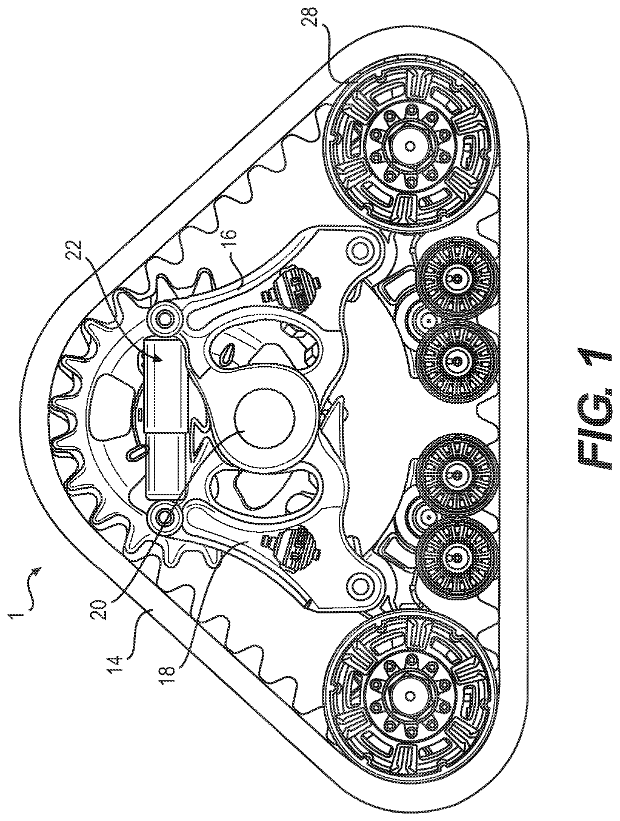
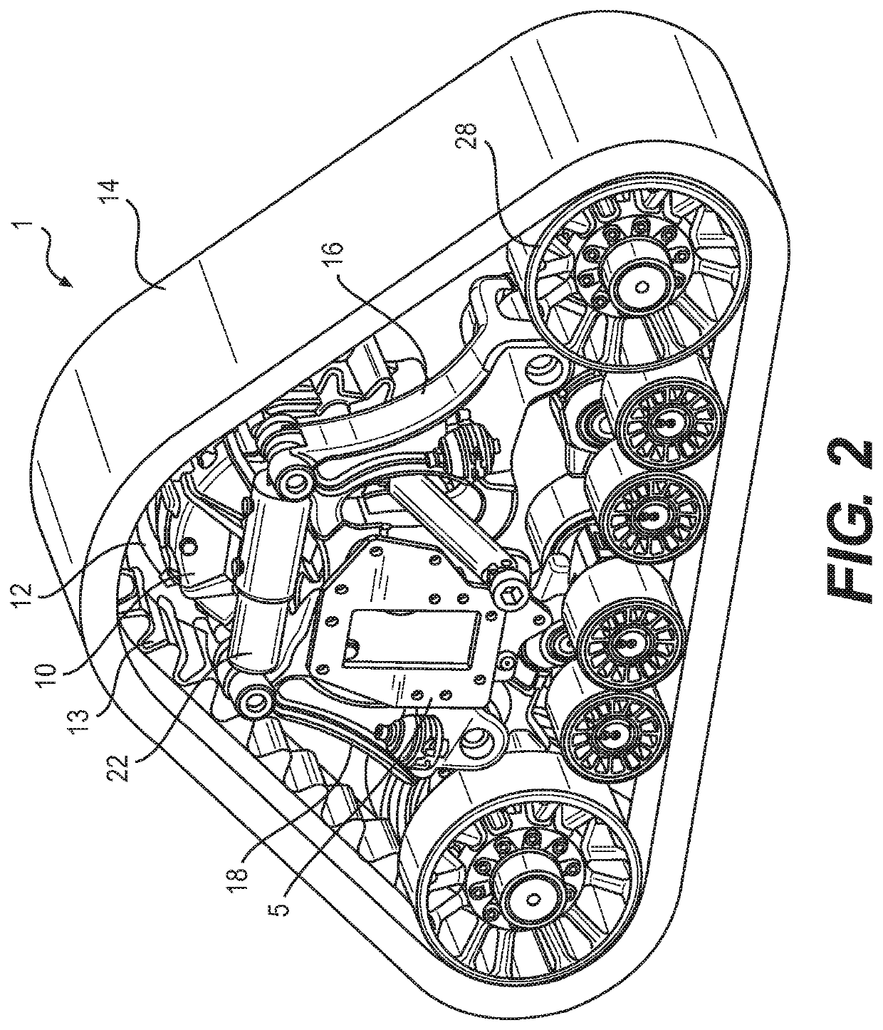
[0039]Referring to FIG. 1, an exemplary track system 1 (a.k.a. track assembly) is shown. The track system 1 is well adapted for an agricultural vehicle such as a tractor, a harvester or any utility cart or trailer. Still, the track system 1 could be mounted to other types of vehicles such as, but not limited to, all-terrain vehicle (ATV), utility-terrain vehicles (UTV), side-by-side vehicles (SSV), and other similar vehicles. The vehicle may be used for different purposes, including agriculture, construction, forestry, mining and powersport. The track system 1 typically comprises a sprocket wheel (not shown) configured to be mounted to the wheel axle or...


PUM


Abstract

The present invention generally relates to vehicle and machinery in agriculture, construction, forestry, mining and powersport. It further generally relates to track systems and traction assemblies used with such vehicles. The track system comprises a drive wheel and a plurality of idler wheels mounted on a support frame. At least one of the plurality of wheels is operatively mounted on the support frame via a damping system adapted to provide a damping value dynamically varying as a function of the load applied. Track systems do not benefit from the damping provided by the layer of air within the tires. The disclosed damping system has the objective to overcome one this drawback by providing a smooth ride for tracked vehicles. The damping system comprises a cylinder fluidly connected to a reservoir. Damping ratio is varied by varying a flow circulating area between the cylinder and the reservoir.

Description

CROSS-REFERENCE TO RELATED APPLICATIONS[0001]The present patent application claims the benefits of priority of commonly assigned Patent Application No. 62 / 146,140, entitled “Progressive damping system for a track system” and filed at the United States Patent and Trademark Office on Apr. 10, 2015, the content of which is incorporated herein by reference.FIELD OF THE INVENTION[0002]The present invention generally relates to track systems for vehicle and machinery in agriculture, construction, forestry, mining and powersport which uses suspension having damping capabilities. More particularly, the present invention may also relate to track systems and traction assemblies which comprise a progressive damping system.BACKGROUND OF THE INVENTION[0003]Traction and flotation have always been important issues with farming and construction vehicles. Having a vehicle mounted on track systems assures lower ground pressure, better traction and better use of the available power. This is particular...

Claims


Application Information

Patent Timeline
Patent Type & Authority Patents(United States)
IPC IPC(8): B62D55/112B62D55/15B60G17/08B62D55/12B62D49/06B60G17/056B60G17/0165F16F9/346F16F9/512F16F9/06B62D55/04
CPCF16F9/065B62D55/15B62D55/04B60G17/056B62D49/0635B62D55/112B60G17/08B62D55/12F16F9/346B60G17/0165F16F9/512B60G2400/25B60G2300/32B60G2500/11B60G2202/154
Inventor SAUVAGEAU, YVESPELLERIN, JONATHAN
Owner SOUCY INT
Features
  • R&D
  • Intellectual Property
  • Life Sciences
  • Materials
  • Tech Scout
  • Unparalleled Data Quality
  • Higher Quality Content
  • 60% Fewer Hallucinations
Learn More