Sensor for detecting an object and method of setting a switching point

a technology of object detection and sensor, applied in the direction of electronic switching, pulse technique, instruments, etc., can solve the problems of method reaches its limits, additional conditions can also become complex, and the minimum distance between the real object and the real background would have to be so large that it cannot even be realized in typical applications of the sensor, so as to achieve the effect of working more reliably and better detecting the situation to be detected

Active Publication Date: 2020-05-05
SICK AG
View PDF22 Cites 0 Cited by
  • Summary
  • Abstract
  • Description
  • Claims
  • Application Information

AI Technical Summary

Benefits of technology

[0010]It is therefore the object of the invention to further develop a sensor such that it works more reliably and can better detect the situation to be detected.
[0014]The invention has the advantage that the manual adjustment is replaced via potentiometers, encoders or a teach button with an automated setting of the switching point. The switching point takes account of the variation of the detection situations and is thereby a lot more flexible and robust. It is no longer necessary that the teaching is cried out by experts having experience for the sensor and for the application. The set switching point can be transmitted to other sensors, for example to a replacement device. The teaching in accordance with the invention of a switching point also works in complex situations with multi-dimensional sensor signals and unclear conditions at an object to be determined. The sensor itself can, however, remain very simple since in operation only the comparisons or classifications predefined by the switching point have to be carried out for its sensor signal. This above all applies when the processing effort of the teaching phase is outsourced to external and the sensor does not have to provided it itself.
[0026]The sensor is preferably a light barrier or a light sensor. It is a frequently used sensor that is simple and proven and that particularly profits from the considerably improved setting of the switching point. The light barrier can be a through beam light barrier or a reflection light barrier; the light sensor can have a background masking or a distance measurement by a time of flight method or by triangulation. Alternatively, the sensor can be an inductive, capacitive, magnetic, ultrasound, or radar sensor.

Problems solved by technology

If all the theoretically conceivable extremes such as black velvet and white, ideally remitting bodies or optical mirrors at any desired angles, and thus all the theoretically possible detection errors and detection differences were taken into account in the setting of the switching point, the minimal distance between the real object and the real background would have to be so large that it cannot even be realized in typical applications of the sensor.
In addition, the method reaches its limits at the latest when even the intuition of an expert fails to imagine still suitable criteria for the determination of the object determination signal in complex situations with the most varied objects or with a plurality of internally available sensor signals.
Like the sensor signal itself, such additional conditions can also become complex and can, for example, depend on the past as in the case of a hysteresis.
Such an additional sensor could possibly also satisfy the application, but would be too expensive or too short-lived.
The installation of the additional sensor is therefore only temporarily possible during the teaching phase.
For example, connector lines of the additional sensor are led in a manner that is not robust enough for everyday operation or that uses provisional support constructions for the sensor or its connectors.
The switching point is derived there, which is very time and processing intensive under certain circumstances.

Method used


Image

  • Sensor for detecting an object and method of setting a switching point
  • Sensor for detecting an object and method of setting a switching point
  • Sensor for detecting an object and method of setting a switching point

Examples


Embodiment Construction

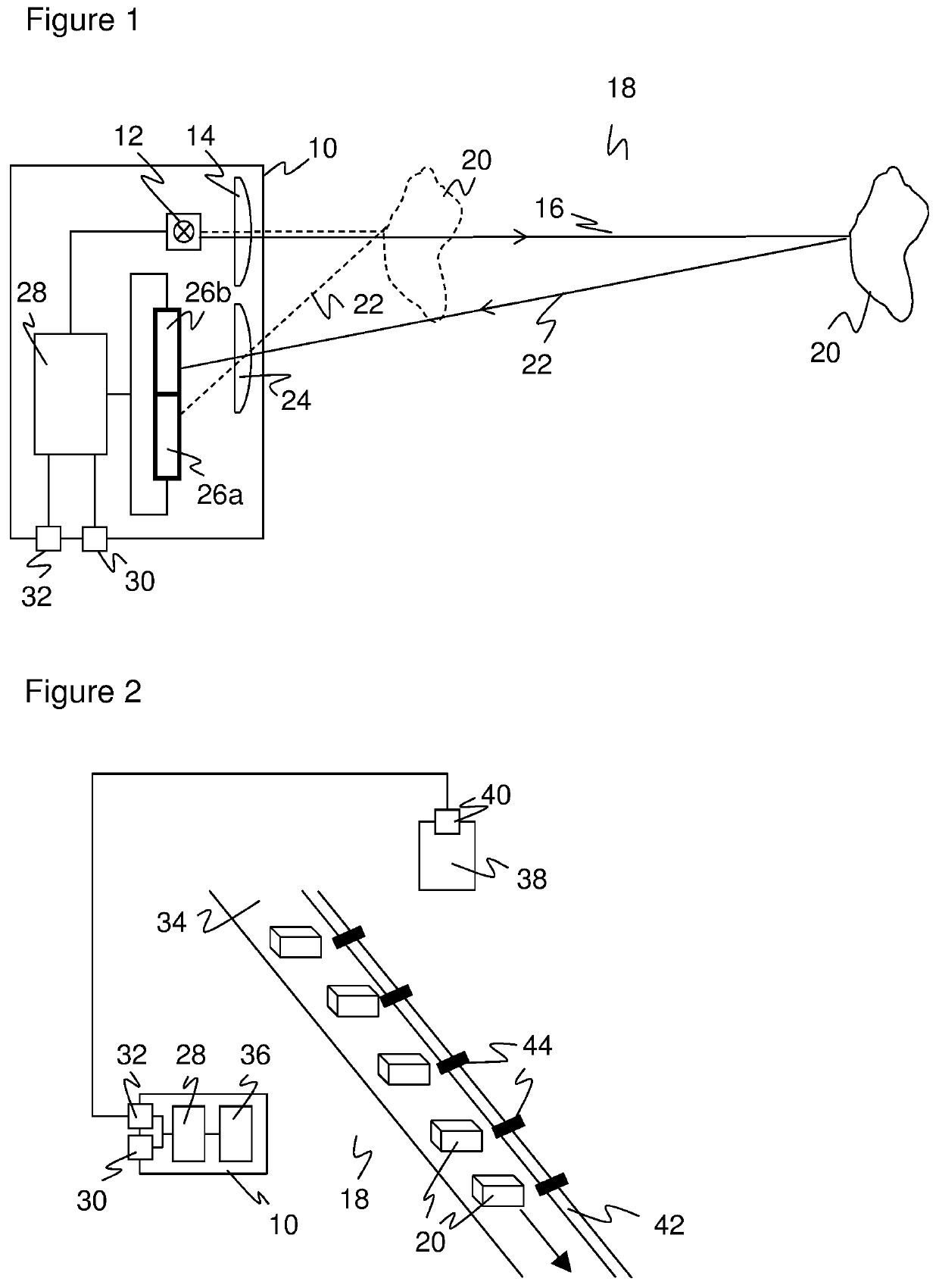
[0035]FIG. 1 shows a schematic sectional representation of a sensor 10 in an embodiment as a conventional triangulation light sensor with background masking. This is only one of a large number of embodiments of a sensor 10 in accordance with the invention with reference to which it should be explained purely by example how a sensor 10 detects an object determination signal by means of a settable switching point. The invention generally comprises sensors that delivery a binary object determination signal such as reflection light barriers, through beam light barriers, or distance-measuring light sensors in accordance with the principle of the time of flight process or of triangulation, but also inductive, capacitive, magnetic, ultrasound, or radar sensors and more.

[0036]In the embodiment of the sensor 10 in accordance with FIG. 1, a light transmitter 12 transmits a light beam 16 into a monitored zone 18 via a beam-shaping transmission optics 14. If the light beam 16 is incident on an ...


PUM


Abstract

A sensor (10) is provided for detecting an object (20) in a monitored zone (18), having at least one sensor element (36) for detecting a sensor signal; having a switch output (30) for outputting a binary object determination signal; and having an evaluation unit (28) that is configured to generate the object determination signal from the sensor signal in dependence on the detected object (20) and to determine, in a teaching phase, a switching point that determines the association between the sensor signal and the object determination signal. The evaluation unit (28) is further configured to detect a respective sensor signal for a plurality of detection situations in the teaching phase, with the associated object determination signal being predefined for the respective detection situation and with the switching point being derived therefrom.

Description

BACKGROUND1. Field[0001]The invention relates to a sensor for detecting an object an object in a monitored zone and to a method of setting a switching point of a sensor that detects objects in a monitored zone.2. Description of the Related Art[0002]The detection of an object is a fundamental function of the most varied sensors, from inductive, magnetic, or capacitive sensors, over ultrasound sensors, up to optoelectronic sensors. There are in turn subfamilies of every physical principle. Optoelectronic sensors include through beam light barriers and reflection light barriers that recognize interruptions or attenuations of a light beam directed onto a light receiver directly or via a reflector. Cameras in a number of variations, including linear cameras and 3D cameras, are also optoelectronic sensors.[0003]A further group is formed by light scanners whose light beam is guided in a scanning manner into the monitored zone and is only registered in a light receiver when an object is loc...

Claims


Application Information

Patent Timeline
Patent Type & Authority Patents(United States)
IPC IPC(8): G01S17/04H03K17/968G01S17/46G01V8/20G01S17/42G01S7/481G01V8/10
CPCG01S17/42G01S17/04G01V8/20G01S17/46G01V8/10H03K17/968G01S7/481H03K2217/965H03K2217/941
Inventor WASLOWSKI, KAI
Owner SICK AG
Why Eureka
Try Eureka