Apparatus for distribution of catalyst in fluidized catalytic cracking unit

a technology of fluidized catalytic cracking and distributor, which is applied in the direction of catalytic cracking, hydrocarbon oil treatment, physical/chemical process catalysts, etc., can solve the problems of catalyst not being regenerated as efficiently, coke getting deposited on the catalyst, cracking, etc., to reduce hotspots and localized catalyst deactivation, improve coke burning, and improve the effect of catalyst distribution

Active Publication Date: 2020-05-12
INDIAN OIL CORPORATION
View PDF8 Cites 0 Cited by
  • Summary
  • Abstract
  • Description
  • Claims
  • Application Information

AI Technical Summary

Benefits of technology

[0017]The advantages of the present invention include, but are not limited to, better spent catalyst distribution across the catalyst regenerator that improves coke burning in the catalyst regenerator thereby minimizing hotspots and localized catalyst deactivation. The present invention achieves a more effective regeneration and a cleaner regenerated catalyst.

Problems solved by technology

In the riser, at high temperature, cracking occurs and coke gets deposited on the catalyst.
It is a known problem in the prior art that if the spent catalyst is not distributed into the regenerator in a uniform manner, the catalyst is not regenerated as efficiently, after-burning and the associated temperature increase in the dilute phase of the regenerator occurs, and NOx, SOx are generated in undesirable amounts.
However, this design, while not in the shape of a spooked wheel, also causes the catalyst to be distributed in the regenerator in a very uneven manner.
Such design of SCD cannot provide even distribution of spent catalyst across the regenerator shell.

Method used


Image

  • Apparatus for distribution of catalyst in fluidized catalytic cracking unit
  • Apparatus for distribution of catalyst in fluidized catalytic cracking unit
  • Apparatus for distribution of catalyst in fluidized catalytic cracking unit

Examples


Embodiment Construction

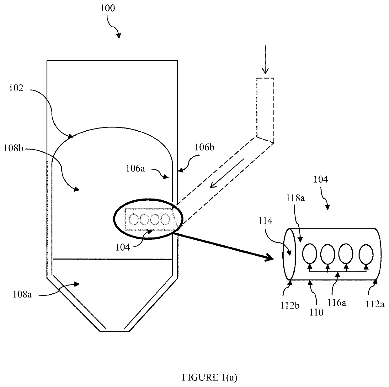
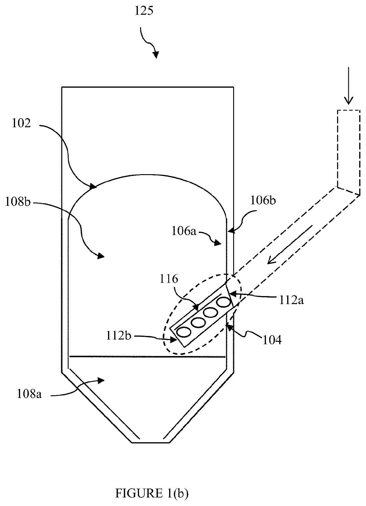
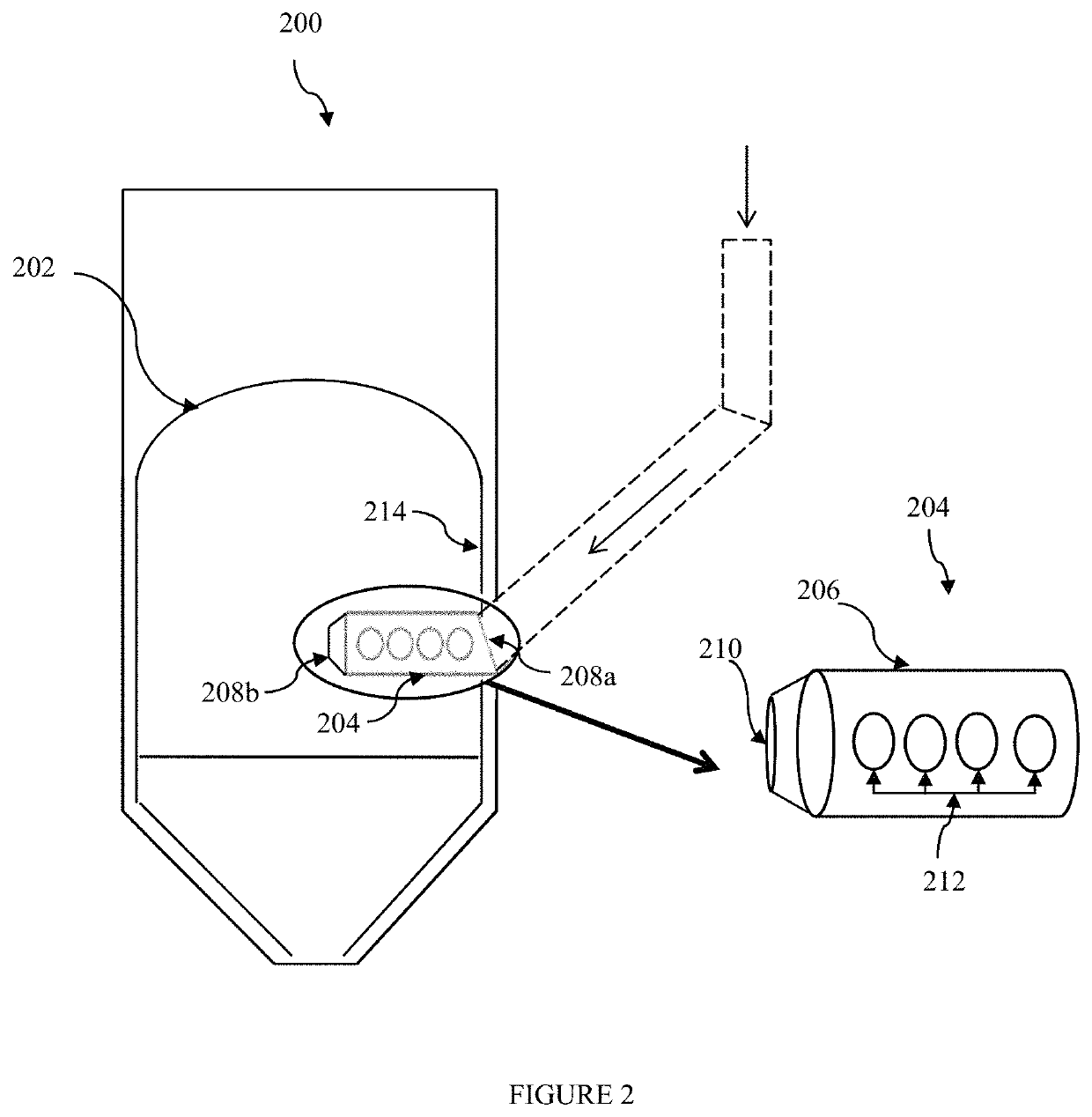
[0026]For the purpose of promoting an understanding of the principles of the invention, reference will now be made to the embodiment illustrated in the drawings and specific language will be used to describe the same. It will nevertheless be understood that no limitation of the scope of the invention is thereby intended, such alterations and further modifications in the illustrated system, and such further applications of the principles of the invention as illustrated therein being contemplated as would normally occur to one skilled in the art to which the invention relates. It will be understood by those skilled in the art that the foregoing general description and the following detailed description are explanatory of the invention and are not intended to be restrictive thereof.

[0027]Reference throughout this specification to “an aspect”, “another aspect” or similar language means that a particular feature, structure, or characteristic described in connection with the embodiment is...


PUM

PropertyMeasurementUnit
anglesaaaaaaaaaa
anglesaaaaaaaaaa
lengthaaaaaaaaaa

Abstract

A spent catalyst distributor for distributing spent catalyst in a catalyst regenerator vessel housing a dense phase catalyst bed and a dilute phase catalyst bed. The spent catalyst distributor comprises a conduit comprising a proximal end and a distal end. The conduit projects horizontally or horizontally and downwardly into the regenerator vessel and includes an opening located at the distal end for introducing the spent catalyst at a first location inside the regenerator vessel. The conduit further includes a plurality of orifices located along a length of the conduit between the distal end and an inner wall of the regenerator vessel for introducing the spent catalyst at a plurality of locations inside the regenerator vessel.

Description

FIELD OF THE INVENTION[0001]The present subject matter relates to a spent catalyst distributor for distributing spent catalyst.BACKGROUND OF THE INVENTION[0002]Spent catalyst distributors are known for many years. In the Fluidized Catalytic Cracking (FCC) process, the catalyst comes in contact with atomized heavy hydrocarbon molecules in the riser. In the riser, at high temperature, cracking occurs and coke gets deposited on the catalyst. Thereafter, the catalyst enters into stripper for removing the entrapped hydrocarbons inside the catalyst pores. The coke laden catalyst leaving the stripper is hereby being referred as “spent catalyst”.[0003]The coke on the spent catalyst, which covers the active sites on the catalyst and thereby substantially reduces the activity of the catalyst. It is possible, however, to remove the coke from the catalyst inside the regenerator by burning with air. The spent catalyst is fed into the regenerator through a “Spent Catalyst Distributor” (SCD) for u...

Claims


Application Information

Patent Timeline
Patent Type & Authority Patents(United States)
IPC IPC(8): B01J38/30B01J8/26C10G11/18B01J8/00B01J8/18
CPCB01J8/26B01J8/004B01J8/1818B01J38/30B01J8/0025B01J8/003C10G11/182B01J8/1809C10G2300/70
Inventor KHAN, SHOEB HUSSAINBADHAN, VIKASBANDARU, VENKATA HARI PRASAD GUPTATHAPA, GAUTAMKUMARAN, SATHEESH VETTERKUNNELBHATTACHARYYA, DEBASISRAMAKUMAR, SANKARA SRI VENKATA
Owner INDIAN OIL CORPORATION
Why Eureka
Try Eureka