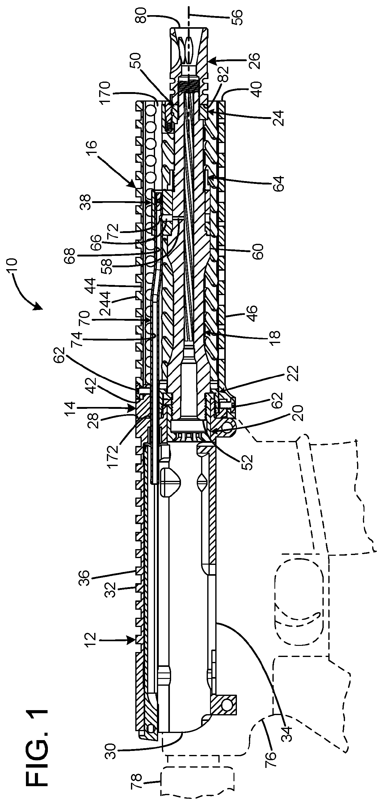
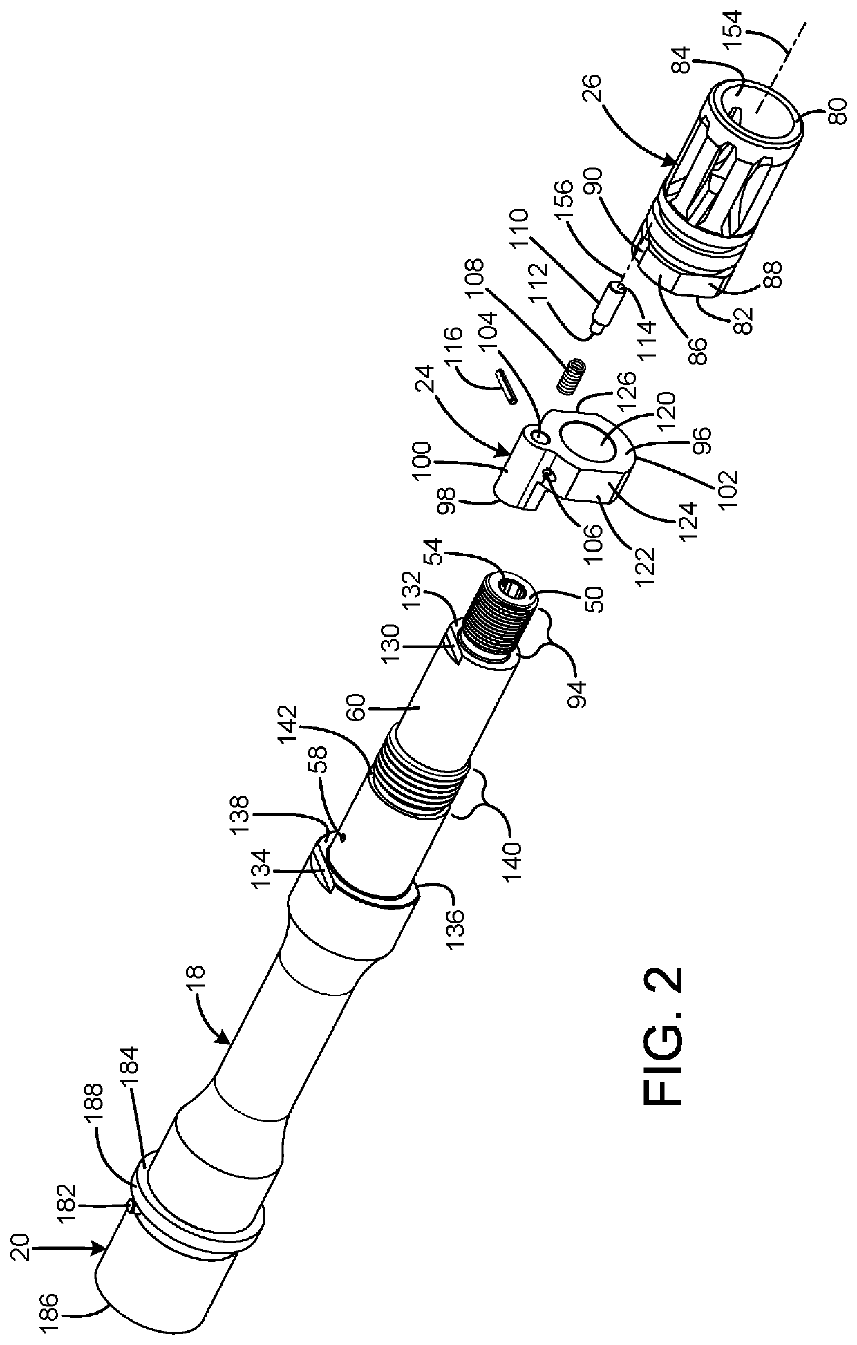
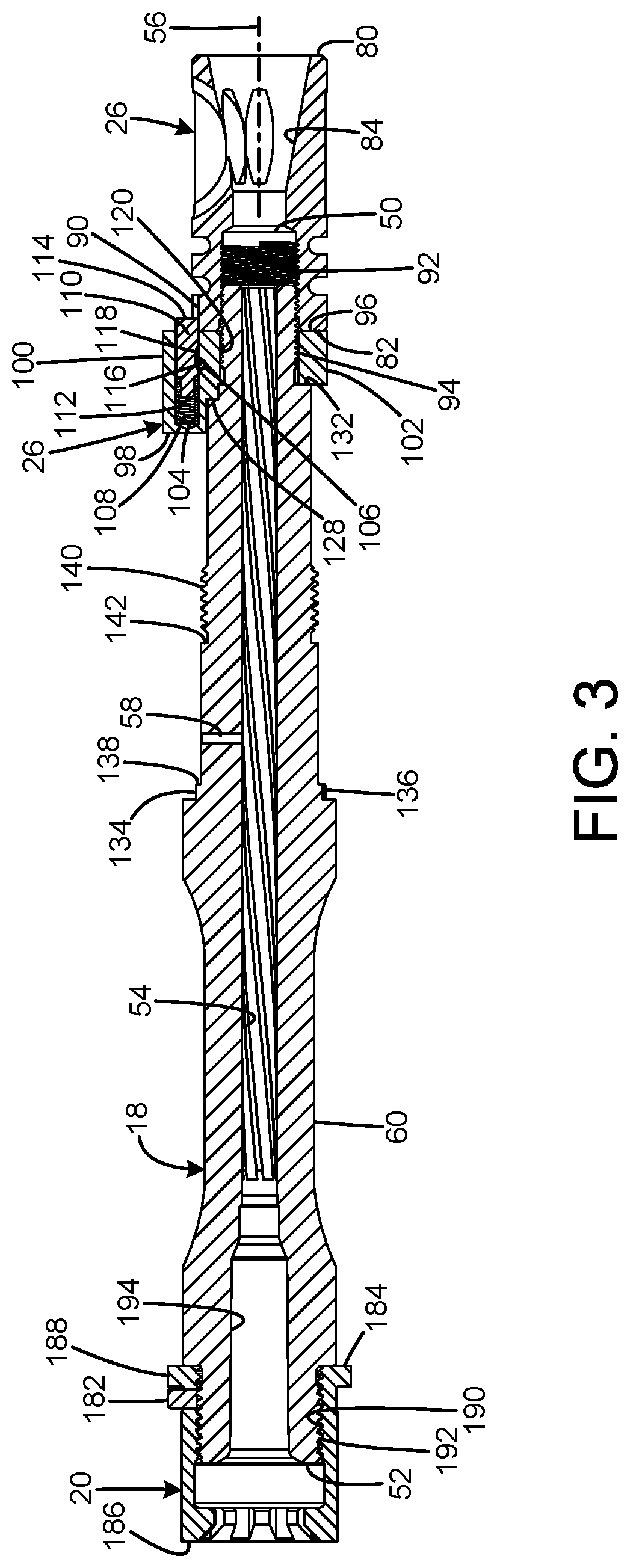
Nevertheless, since the original inception of the AR-15, M16 / M4 variants, there remains an impractical design flaw which continues to be incorporated into every revision, improvement or reconfiguration of these platforms.
This design inherently impairs simple removal and / or replacement of muzzle devices.
If the device is tightened past an intended position, or requires reorientation, retarding the muzzle device away from a previous
washer crush or collapse could render the crush
washer unserviceable, as previous tension would be lost.
Additionally, use of a crush
washer may require
cutting the washer from the barrel upon removal, as the crush action oftentimes deforms the washer around the threaded barrel, lower than the maximum thread
diameter of the barrel, thus further impeding removal.
Cosmetic damage to the barrel's finish can result because use of a tool to
cut off the used crush washer is frequently required.
This orientation process is problematic because the gas tube may be slightly misaligned, permitting interference with the gas key on the BCG, thus allowing undesired friction and / or drag of the components.
Likewise, and possibly more consequential, would be the compromised leaking of ballistic
gas pressure between the gas tube and gas key, thus reducing the effectiveness of the direct gas impingement
system cycle.
Affixing the gas block to the barrel within current industry standards is also problematic in that set screws are commonly used for this function.
Considering set screws are limited to lateral pressure in one direction, their application creates a
high probability of
set screw force negating proper concentricity of gas block and barrel alignment.
As such, a compromised seal between the gas block and barrel is often created, which negatively impacts the effectiveness of the direct gas impingement
system cycle.
Small set screws, typically ¼″ and smaller, are commonly used in gas block installations and are prone to overtightening,
seizing, and stripping of the drive profile.
It is not uncommon that seized or damaged set screws may require the gas block to be
cut from the barrel to remove the gas block, which requires gas block replacement and can potentially damage the barrel.
Furthermore, tightening the
set screw onto the
radial surface of the barrel can also negatively
impact gas block alignment as the screws tightening rotational direction on the
radial surface can cause the gas block to twist upon installation.
However, the overtightening,
seizing and / or stripping of the
set screw drive profile remains a problematic condition, as does the unfavorable conditions regarding gas block distorting and subsequent ballistic
gas pressure compromise.
As there exists no standardized pattern or set screw spacing within the firearms industry, barrel alterations regarding pocket depressions or dimples may cause mismatched conditions, including inappropriate positioning on commercially available, non-standardized gas blocks.
Additionally, misaligned gas blocks can also prevent appropriate handguard installation because internal profiles of handguards tend to be limited in space and require a close and parallel and / or perpendicular alignment with the gas block.
When a gas block's orientation prohibits handguard installation, the gas block must be reoriented, further compounding the previously stated detrimental conditions.
Finally, the current
industry standard for gas block captivation can provide less than adequate mechanical holding force when hardware (i.e. set screws) has been compromised.
Gas block movement and subsequent loss of operating
gas pressure commonly occurs under these circumstances.
The slotted clamp force design is problematic because clamping forces are not applied concentrically around the barrel nut's base, thus distorting and often
seizing the handguard around the barrel nut, which impedes removal or adjustment.
This condition also negatively alters handguard to barrel alignment.
The extended design of the barrel nut also adds additional weight to the firearm.
Overtightening often occurs when attempting proper alignment, or a shim may be required to time thread engagement with port alignment.
This design commonly requires a special tool, such as a spanner
wrench, to install or remove the handguard; which further complicates installation, removal, or adjustment of the handguard.
While this design offers more consistent and evenly dispersed clamping force, the design does not address handguard alignment and permits misaligned handguard installation.
When a handguard is misaligned, it is often difficult to access the driving profile of the hardware to secure the handguard.
With any conventional handguard design, the inability to repeatably ensure a specified alignment creates further complications when an optical aid or sighting device (e.g. flip-up
sight post,
laser sight, etc.) is mounted to the handguard.
When the handguard cannot be repeatably removed and reattached to a firearm in a specified alignment, sighting devices must be recalibrated or zeroed once a handguard installation has been compromised or altered.
While many prior art handguard mounting designs exist, including other variations not specifically discussed, existing handguard designs do not ensure rigid application, repeatable installation, control of proper alignment, and ease of use.


