
Magnetic resonance imaging device and RF coil assembly with matching switch circuit and tuning switch circuit

a technology of magnetic resonance imaging and matching switch circuit, which is applied in the field of magnetic resonance imaging device, can solve the problems of limited range of simultaneous imagers, limited range where high image quality is obtained, and achieves low sar, high sn ratio, and high emission efficiency

Active Publication Date: 2020-05-19
FUJIFILM HEALTHCARE CORP
View PDF16 Cites 3 Cited by
  • Summary
  • Abstract
  • Description
  • Claims
  • Application Information

AI Technical Summary

Benefits of technology

The invention provides a way to make an RF coil that can still perform well even if it is bent or deformed. This is especially useful for a reception coil, where the shape of the subject being imaged can vary. The coil can maintain a high signal-to-noise ratio (SN ratio) and remain well-matched to the subject being imaged. It can also be used as a transmitting coil and achieve high efficiency with low specific absorption rate (SAR). Additionally, if a switch is provided for switching between emission and reception, the coil can achieve both high efficiency and a high SN ratio regardless of the shape of the coil or the subject being imaged. The invention also enables the creation of flexible RF coils that can perform equally well in different parts of the body and at low cost for use in patient fixtures.

Problems solved by technology

A range capable of being simultaneously imaged is limited to the range of the static magnetic field space at most, and a range where high image quality is obtained is limited to the sensitivity range of the RF reception coil.
This is because if the electromagnetic coupling between the coil elements is present, noise interference occurs between the coil elements, and thus, the SN ratio of an image deteriorates.
Particularly, in the case of the RF coil having the above-described wide sensitivity range, since the size is large and the weight is heavy, the workload of the operator who carries the RF coil is increasing.
Further, when a positional relationship between the subject and the coil is not correct, it is necessary to separate the subject from the coil and to perform resetting.
However, in the case of an “upper coil” disposed above the subject in the body thickness direction, the “upper coil” becomes an obstruction in setting the subject.

Method used


Image

  • Magnetic resonance imaging device and RF coil assembly with matching switch circuit and tuning switch circuit
  • Magnetic resonance imaging device and RF coil assembly with matching switch circuit and tuning switch circuit
  • Magnetic resonance imaging device and RF coil assembly with matching switch circuit and tuning switch circuit

Examples


first embodiment

[0047]First, an MRI apparatus according to a first embodiment of the invention will be described with reference to FIGS. 1 to 10.

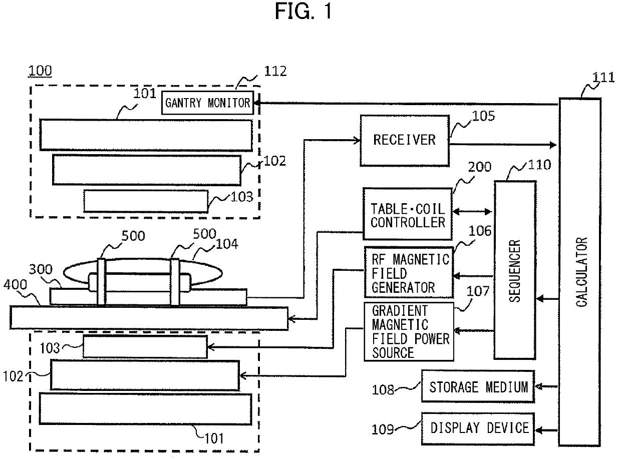
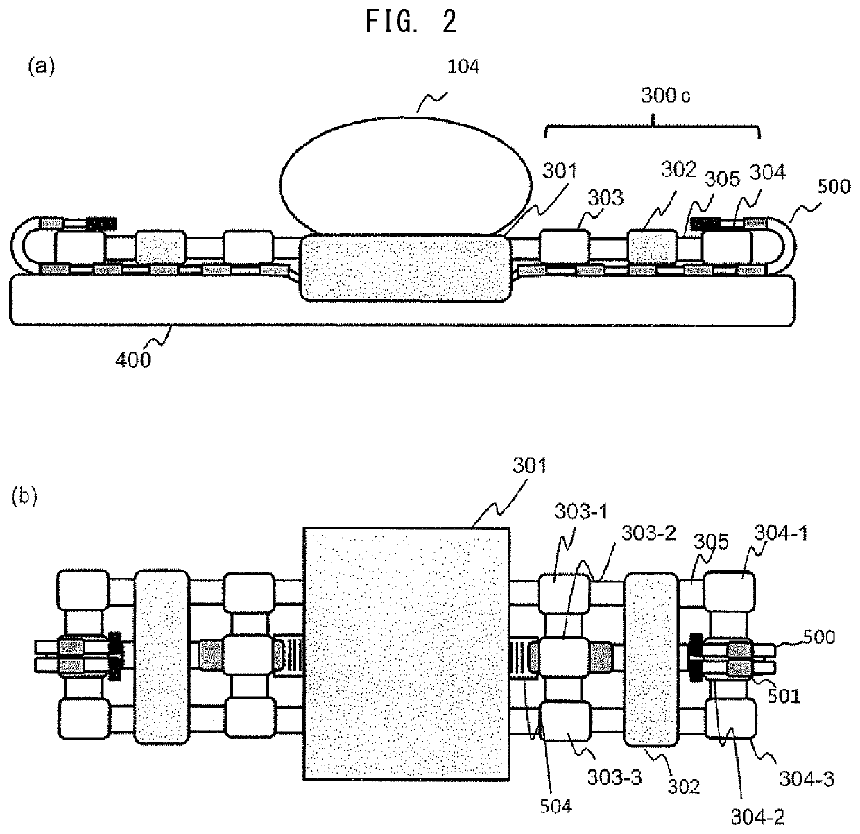
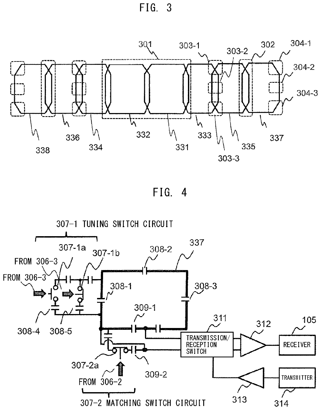
[0048]The MRI apparatus of the first embodiment includes a gantry 100 provided with a static magnetic field generator (101) that generates a static magnetic field and a gradient magnetic field generation coil 102 that generates a gradient magnetic field, a table 400 that is disposed in the gantry 100 for mounting a test object 104 thereon, and an RF coil 300 that receives a nuclear magnetic resonance signal generated from the test object 104 (FIG. 1). The RF coil 300 is configured so that a part (301) thereof is fixed to the gantry 100 or the table 400 and at least another part (300c) thereof is formed of a flexible material and is deformable to be in contact with the test object 104 (FIGS. 2(a) and 2(b), and FIG. 3). Further, the MRI apparatus includes a fixture 500 for fixing the RF coil 300 around the test object 104, a detector (306 and 505) that detec...

second embodiment

[0064]Hereinafter, a second embodiment will be described with reference to FIGS. 11 to 18.

[0065]In the second embodiment, a detector (306b and 505b) includes an RF coil-side connector 306 provided to be ancillary to an RF coil 300, a fixture-side connector 505 provided to be ancillary to a fixture 500, and coaxial switch connectors (316b, 317b, and 513b) that transmit a control voltage supplied through an interconnection of the fixture 500 when the RF coil-side connector 306 and the fixture-side connector 505 are connected to each other (FIGS. 11, 12, and 15). A matching switch circuit 307b-2 and a tuning switch circuit 307b-1 have a circuit configuration that varies according to the control voltage transmitted from the coaxial switch connectors (316b, 317b, and 513b). Thus, matching circuits 309-1 and 309-2 and tuning circuits 308-1 to 308-5 are respectively switched into an optimal matching state and an optimal tuned state in a shape of the RF coil 300 corresponding to a connectio...

third embodiment

[0074]FIG. 19 shows a RF coil 300 of a third embodiment, in which FIG. 19(a) is a sectional view thereof, and FIG. 19(b) is a plan view (top view). The RF coil 300 of the third embodiment is a two-dimensional array type coil in which coil elements are arranged in a transverse direction and in a body length direction of a subject. The shown coil is an array type coil (3 columns and 8 rows) in which eight coil elements are arranged in a row direction (8 rows) and three of these are arranged in a column direction (3 columns). Similar to the first embodiment, a portion covered with a resin case 301 of the RF coil 300 is fixed to a patient table 400, but a portion other than the covered portion may be used to be wound around a subject 104. That is, a coil array portion 300c of the RF coil 300 is flexible. Belt-shaped fixtures 500-1 and 500-2 are respectively provided on both sides at two positions in the body length direction, and fix the RF coil 300 wound around the subject 104 from out...


PUM


Abstract

In a magnetic resonance imaging device provided with a deformable RF coil permanently mounted on a patient table, the RF coil can constantly maintain a matching state and a tuned state in a state of being flat on a top plate and in a state of being wound around a test object. Coil-side connectors 306-2 and 306-3 provided in a deformable RF coil 300 form a detector in cooperation with any one of fixture-side connectors 506-1 to 506-6, in which the detector detects a fitted state therebetween. A tuning circuit and a matching circuit of coil elements of the RF coil 300 are switched by an output of the detector to change tuning and matching parameters, and to maintain a matching state and a tuned state with respect to a state change indicating that the RF coil 300 is in a wound state.

Description

TECHNICAL FIELD[0001]The invention relates to a magnetic resonance imaging device (MRI apparatus), and more particularly, to a radio frequency coil (RF coil) used on a patient table and a fixture therefor.BACKGROUND ART[0002]An MRI apparatus is an apparatus that applies a gradient magnetic field and an excitation radio frequency magnetic field to a subject disposed in a uniform static magnetic field space in a shield room, receives a nuclear magnetic resonance signal generated using a nuclear magnetic resonance phenomenon by a radio frequency coil (RF reception coil), and images a test object. A range capable of being simultaneously imaged is limited to the range of the static magnetic field space at most, and a range where high image quality is obtained is limited to the sensitivity range of the RF reception coil.[0003]As performance characteristics which are necessary in the RF reception coil, there are SN ratio for high image quality, wide sensitivity range for wide-field imaging...

Claims


Application Information

Patent Timeline
Patent Type & Authority Patents(United States)
IPC IPC(8): A61B5/055G01R33/36G01R33/34
CPCG01R33/3664G01R33/34084A61B5/0555G01R33/3628A61B5/055
Inventor DOHATA, MASAYOSHISOUTOME, YOSHIHISA
Owner FUJIFILM HEALTHCARE CORP
Learn More