Pulley wheel rack

a technology of pulley wheels and pulleys, which is applied in the direction of machine supports, belts/chains/gearrings, portable lifting, etc., can solve the problems of rope wear in an unexpected and wrong way, time-consuming, etc., and achieve the effect of reducing the alignment time of pulley wheels, reducing the risk of heavy objects being moved, and reducing the amount of heavy lifting

Active Publication Date: 2020-05-19
KONE CORP
View PDF18 Cites 0 Cited by
  • Summary
  • Abstract
  • Description
  • Claims
  • Application Information

AI Technical Summary

Benefits of technology

[0024]The aligning time of pulley wheels may be significantly decreased compared to the solutions typically employed, such as shimming. Once the pulley wheel has been installed in place, there is no need to lift the wheel or the wheel rack to find an optimal position—thus the need for heavy lifting work and potentially dangerous moving of heavy objects is minimized.
[0025]The adjusting may be done more accurately as the centre point or middle point of the pulley wheel axis is not affected contrary to the current solution of adjusting the alignment with screws. Therefore it is easier to control the tilt and toe angles during the aligning operation. The position of the pulley wheel rack does not move in relation to the ground during the alignment of tilt and toe angles.

Problems solved by technology

With shimming plates, the pulley wheel may have to be raised several times until a proper position is achieved, which is not only time consuming but also involves heavy lifting work.
The aligning must be done with great care, since an inadequately aligned rope may run asymmetrically causing the rope to wear in an unexpected and wrong way.

Method used


Image

  • Pulley wheel rack
  • Pulley wheel rack
  • Pulley wheel rack

Examples


Embodiment Construction

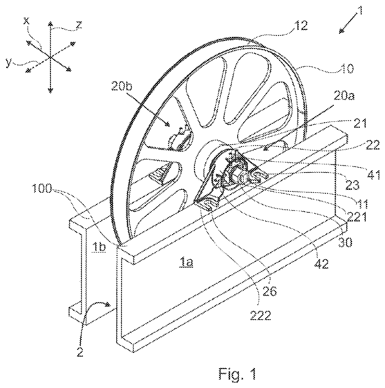
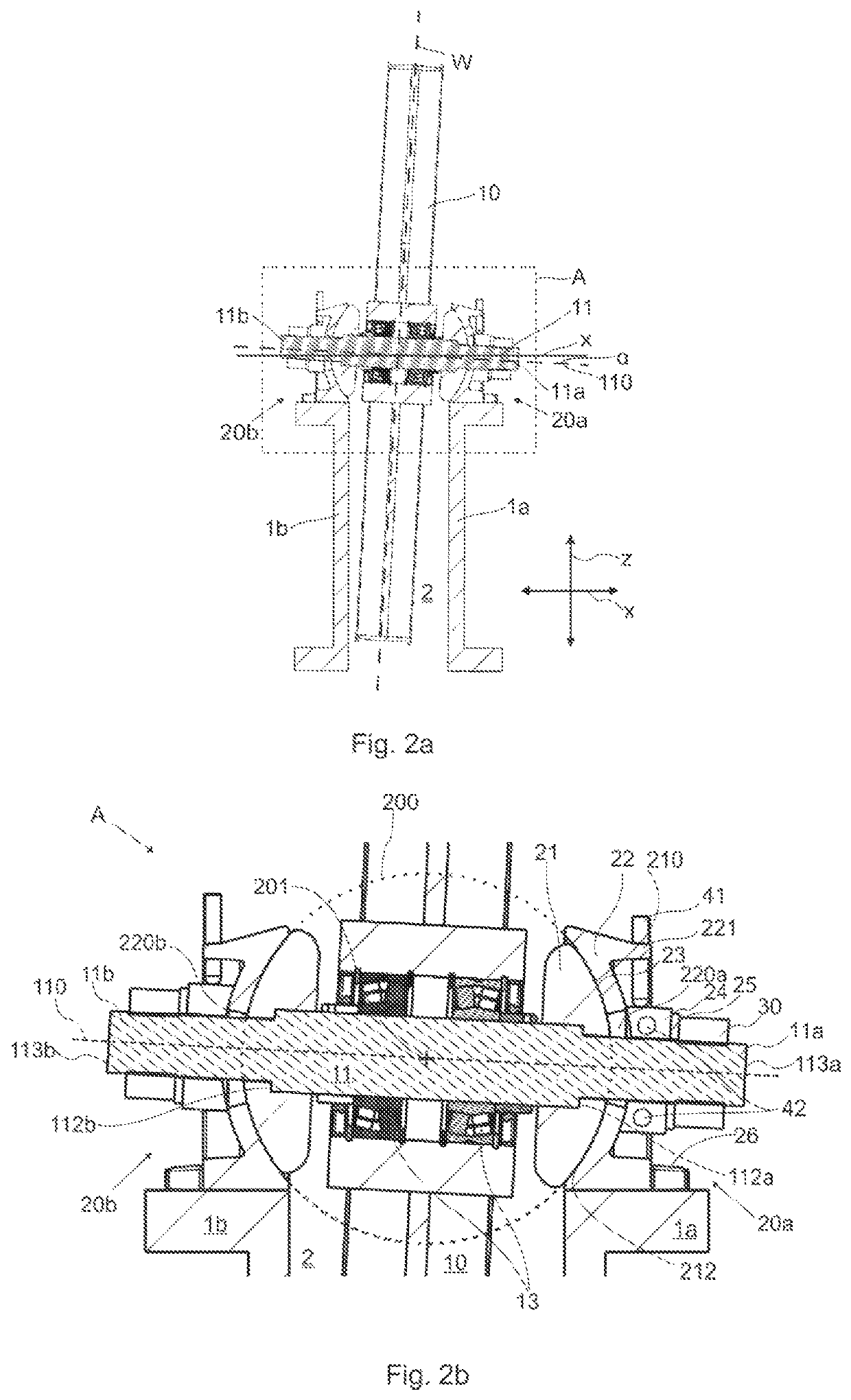
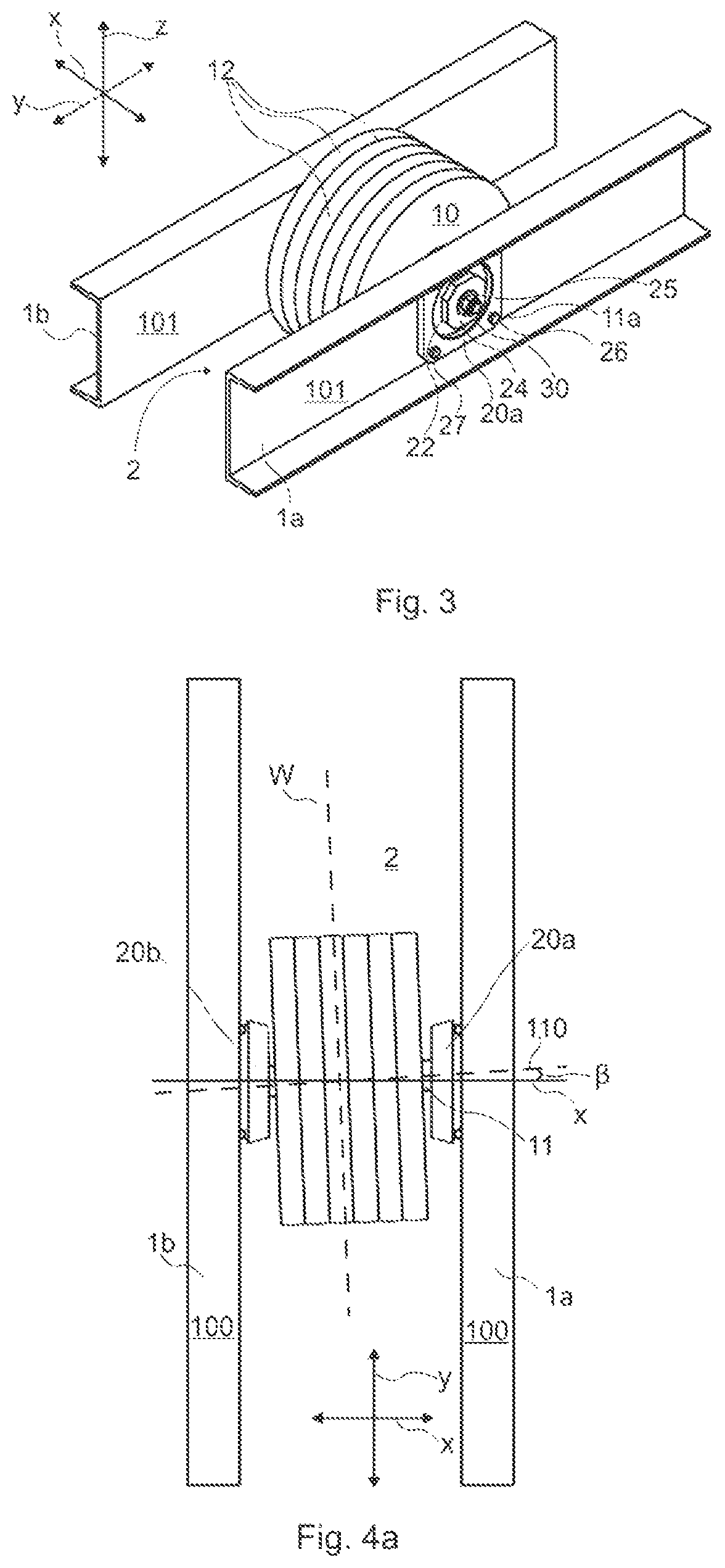
[0036]In the following, certain directional definitions are used to describe the invention in detail. A three-dimensional Cartesian coordinate system is utilised to illustrate the different directions, i.e. an ordered triplet of lines or axes that are pair-wise perpendicular and have an orientation for each axis have been chosen. In relation to a common origin, each of the three axes have a positive (+) direction and a negative (−) direction.

[0037]In the figures, for axis z, the positive direction is interpreted as “upwards” and the negative direction as “downwards” when viewing the invention from a front view; for axis x, the positive direction is “right” and the negative direction “left” (in two-dimensional presentations) in the same viewing direction; and for the axis z, positive direction is interpreted as “forward”, or towards the viewer, and the negative direction is “backward”, i.e. away from the viewer.

[0038]Further, axis z corresponds to vertical; axis x corresponds to hori...


PUM


Abstract

A pulley wheel rack includes a first rack part and a second rack part; a pulley wheel space between the first rack part and the second rack part; a first frame arranged to the first rack part, and a second frame arranged to the second rack part; an axle configured to extend from the first frame to the second frame, and configured to be rotatable into different securable positions by a ball joint arranged into the first frame and the second frame; and a pulley wheel bearing-mounted on the axle by hub bearings, and including at least one traction surface for engaging an elevator rope. A method for aligning a pulley wheel in a pulley wheel rack is also disclosed.

Description

TECHNICAL FIELD[0001]The present disclosure relates to a pulley wheel rack and a method for adjusting the alignment of a pulley wheel. Particularly, the pulley wheel rack and the method are intended for elevators, for example elevators meant for transporting passengers and / or goods.BACKGROUND OF THE INVENTION[0002]An elevator typically comprises an elevator shaft into which an elevator car and / or a counterweight are arranged vertically movable, a driving unit with which the elevator car is moved. The driving unit may comprise a motor and a driven rope wheel engaging elevator suspension or hoisting roping. The roping is arranged between elevator car and the counterweight. The driving force of the motor is transmitted to the car via the driven rope wheel.[0003]In addition, there may be one or more stationary pulley wheels, mounted in the proximity of the upper end of the elevator shaft, for guiding and aligning the suspension roping along the vertical direction of the elevator shaft. ...

Claims


Application Information

Patent Timeline
Patent Type & Authority Patents(United States)
IPC IPC(8): B66B15/02F16M13/02F16C11/06F16H55/52B66B9/00B66B15/04
CPCF16H55/52F16M13/02F16C11/06B66B15/02B66B15/04B66B9/00B66B7/02B66B7/023
Inventor RENVALL, JANIKOSKINEN, ANTTI
Owner KONE CORP
Why Eureka
Try Eureka