Seal arrangement for a gas turbine

a gas turbine and sealing arrangement technology, applied in the field of sealing arrangements, can solve the problem that the conventional sealing arrangement as described above is not an option for components made of alternative materials, and achieve the effect of increasing material thickness and different thermal expansion coefficien

Active Publication Date: 2020-05-19
MTU AERO ENGINES GMBH
View PDF15 Cites 1 Cited by
  • Summary
  • Abstract
  • Description
  • Claims
  • Application Information

AI Technical Summary

Benefits of technology

[0007]In that context, the first sheet-metal element serves as a type of extension of the first securing section. Thus, the first sheet-metal element runs essentially along the first overlapping section such that the sheet-metal element can at least partially close an intermediate space existing between the first component and the second component. The provision of a first sheet-metal element which is arranged along the first securing section permits simple sealing of the intermediate space between the two components made of ceramic fiber composite materials (CMC).
[0013]The first sheet-metal element and / or the second sheet-metal element may be connected to the relevant securing section by rivet connections. To that end, openings are provided in the respective first and / or second securing section. The openings can be formed as a circular hole or as a slot. The first and / or the second sheet-metal element can be made of any metallic or intermetallic material. Thus, it / they can also have a different thermal expansion coefficient to the first and / or the second component. The openings in the form of a slot make it possible to compensate for different thermal expansions.
[0014]An increased material thickness may be provided on the first overlapping section and / or on the second overlapping section. An increased material thickness of this kind serves in particular to permit mechanical rework on the CMC components, in the region of the overlap, without damaging the components. The increased material thickness therefore serves as a type of equalizer for laminate tolerances in the two components made of ceramic fiber composite materials.

Problems solved by technology

However, the production of such blind bores by sinker electrical discharge machining is possible only in electrically conductive materials.
Accordingly, conventional seal arrangements as described above are not an option for components made of alternative materials.

Method used


Image

  • Seal arrangement for a gas turbine
  • Seal arrangement for a gas turbine
  • Seal arrangement for a gas turbine

Examples


Embodiment Construction

[0025]The particulars shown herein are by way of example and for purposes of illustrative discussion of the embodiments of the present invention only and are presented in the cause of providing what is believed to be the most useful and readily understood description of the principles and conceptual aspects of the present invention. In this regard, no attempt is made to show details of the present invention in more detail than is necessary for the fundamental understanding of the present invention, the description in combination with the drawings making apparent to those of skill in the art how the several forms of the present invention may be embodied in practice.

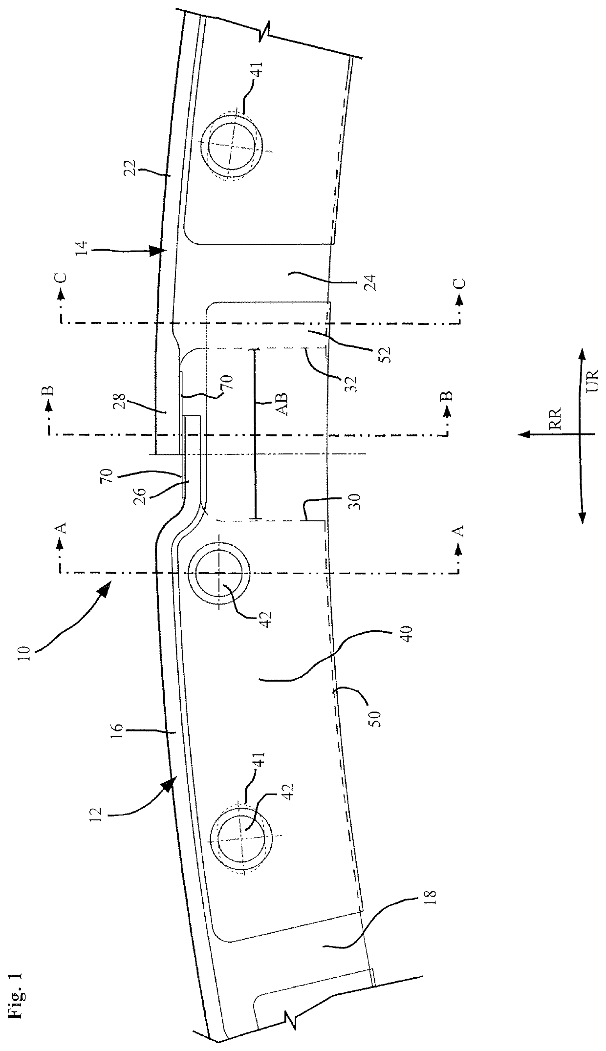
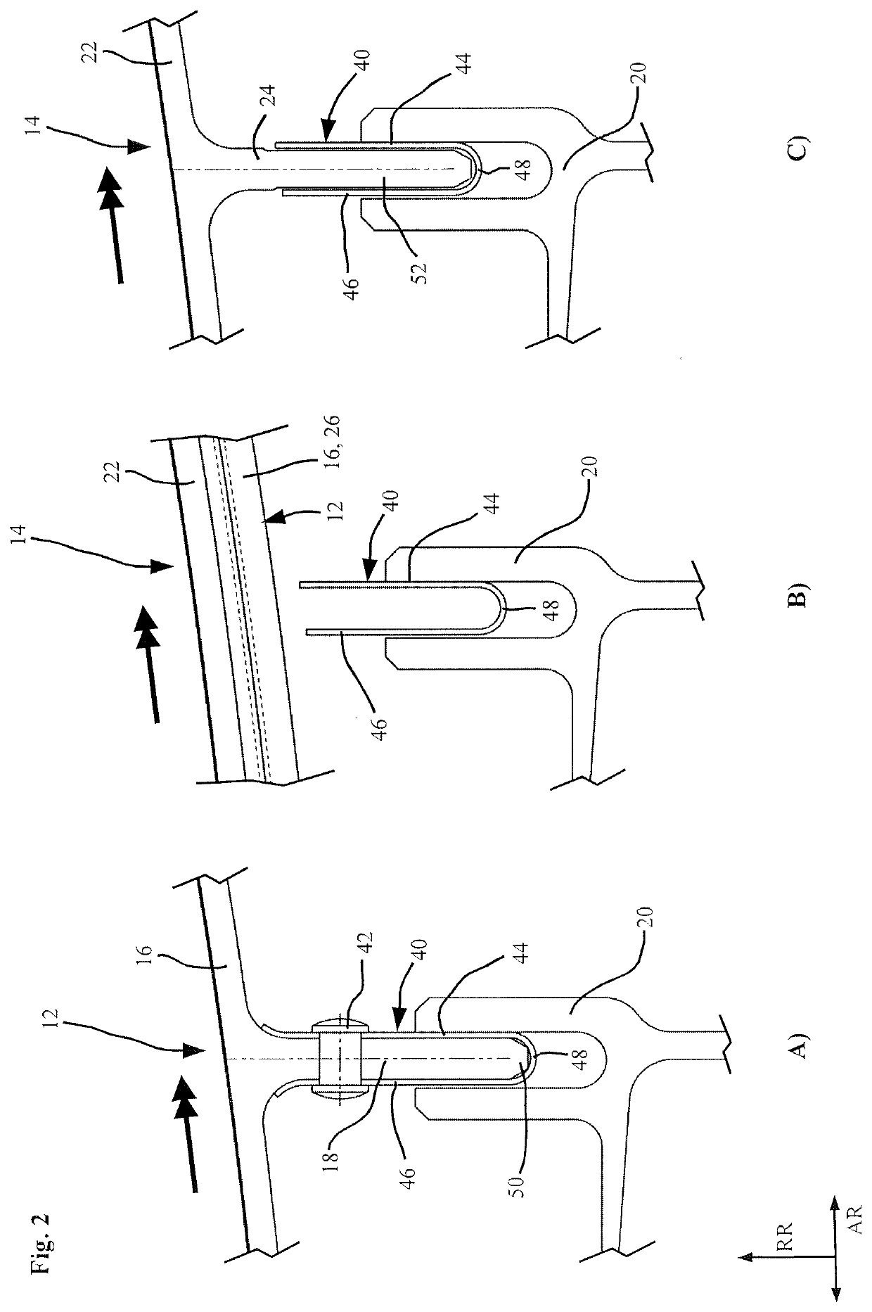
[0026]There follows a description of a seal arrangement 10 with reference to FIG. 1 and the associated sectional depictions of FIG. 2A) to 2C). FIG. 1 shows, in a frontal view, a seal arrangement 10 having a first component 12 and a second component 14. The two components 12, 14 may for example be part of a turbine interme...


PUM


Abstract

A seal arrangement comprising a first and second components made of a ceramic fiber composite material and comprising first and second bounding sections with first and second overlapping sections and first and second securing sections which are connected to and projects from the first and second bounding sections. The first and second overlapping sections are arranged at least partially overlapping such that the first and second bounding sections form an essentially continuous bounding surface. A separation between the first and second securing sections is at least partially sealed by a seal element which comprises at least one first sheet-metal element arranged along the first securing section and at least partially bridging the separation between the first and second securing sections.

Description

CROSS-REFERENCE TO RELATED APPLICATIONS[0001]The present application claims priority under 35 U.S.C. § 119 of European Patent Application No. 17156720.9, filed Feb. 17, 2017, the entire disclosure of which is expressly incorporated by reference herein.BACKGROUND OF THE INVENTION1. Field of the Invention[0002]The present invention relates to a seal arrangement comprising: a first component and a second component, the first component comprising a first bounding section with a first overlapping section and a first securing section that is connected to and projects from the bounding section, the second component comprising a second bounding section with a second overlapping section and a second securing section that is connected to and projects from the bounding section. The first overlapping section and the second overlapping section are arranged at least partially overlapping such that the first bounding section and the second bounding section form an essentially continuous bounding s...

Claims


Application Information

Patent Timeline
Patent Type & Authority Patents(United States)
IPC IPC(8): F01D11/00F16J15/02F01D9/04F16J15/08F01D25/24F01D11/08
CPCF01D11/006F16J15/02F16J15/08F01D11/005F01D9/04F05D2220/32F05D2240/11F05D2300/6033F05D2240/55Y02T50/672F01D11/08F01D25/246F05D2240/57F16J15/0887Y02T50/60
Inventor BOECK, ALEXANDER
Owner MTU AERO ENGINES GMBH
Why Eureka
Try Eureka