
Folding wheelchair

a wheelchair and folding technology, applied in the field of folding wheelchairs, can solve the problems of generating a high tension on the back cover, affecting the use of modern, energy-efficient wheelchairs, and the movement of the back tube of the wheelchair,

Active Publication Date: 2020-06-02
HORACEK GREGOR
View PDF11 Cites 4 Cited by
  • Summary
  • Abstract
  • Description
  • Claims
  • Application Information

AI Technical Summary

Benefits of technology

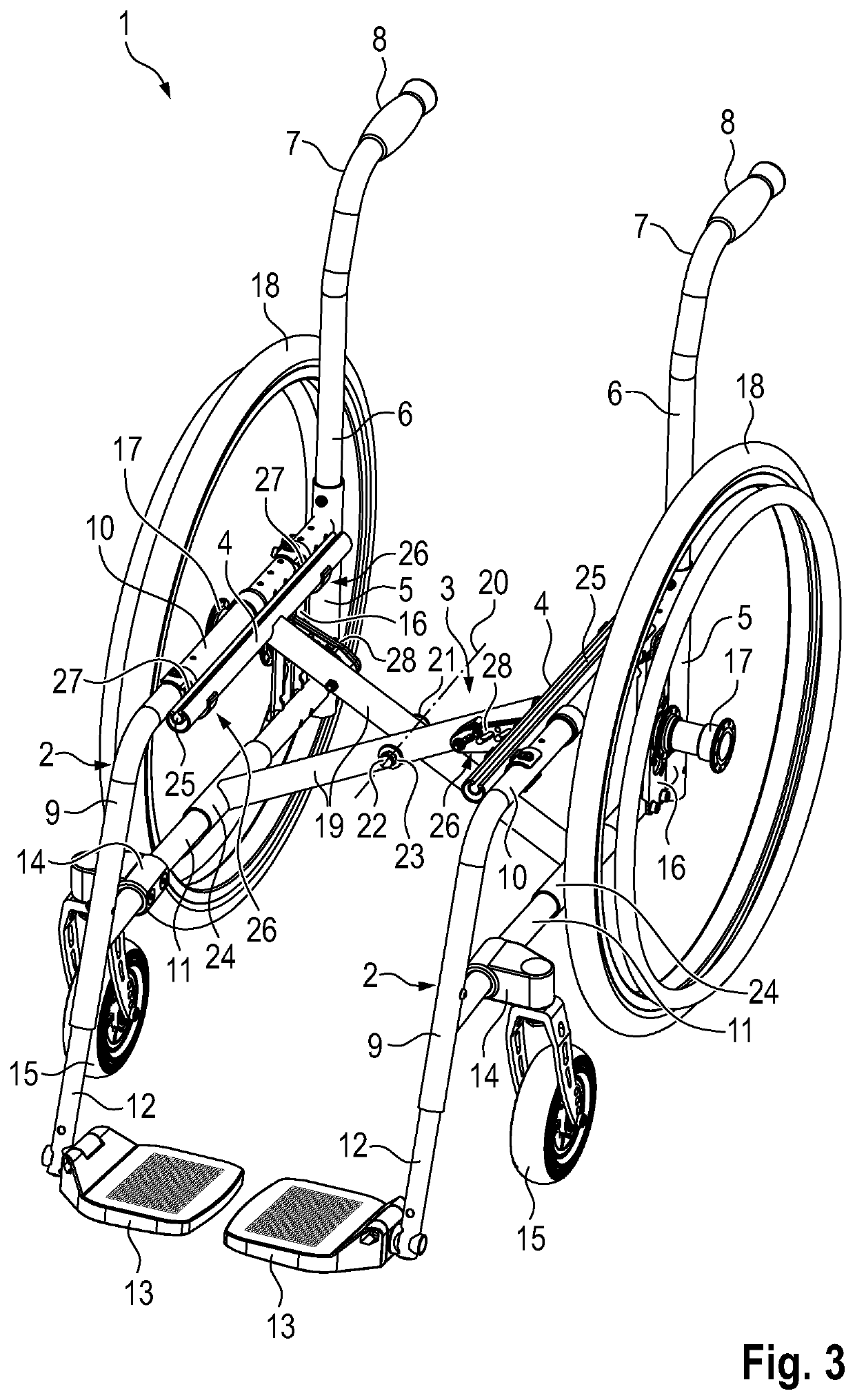
The present invention relates to a foldable wheelchair that avoids disadvantages and allows for parallel guidance of the side frames during the folding process. The design of the wheelchair ensures that the back cover is not subjected to excessive tension, and structural elements of the wheelchair are not subjected to excessive load, in any phase of the folding process. The seat tube bearing is designed to be upwardly open in order to move the seat tube in when unfolding the wheelchair with a movement component directed toward the opening of the seat tube bearing. The guide pin is used as both a fastening element to reduce parts variety and assembly optimization.

Problems solved by technology

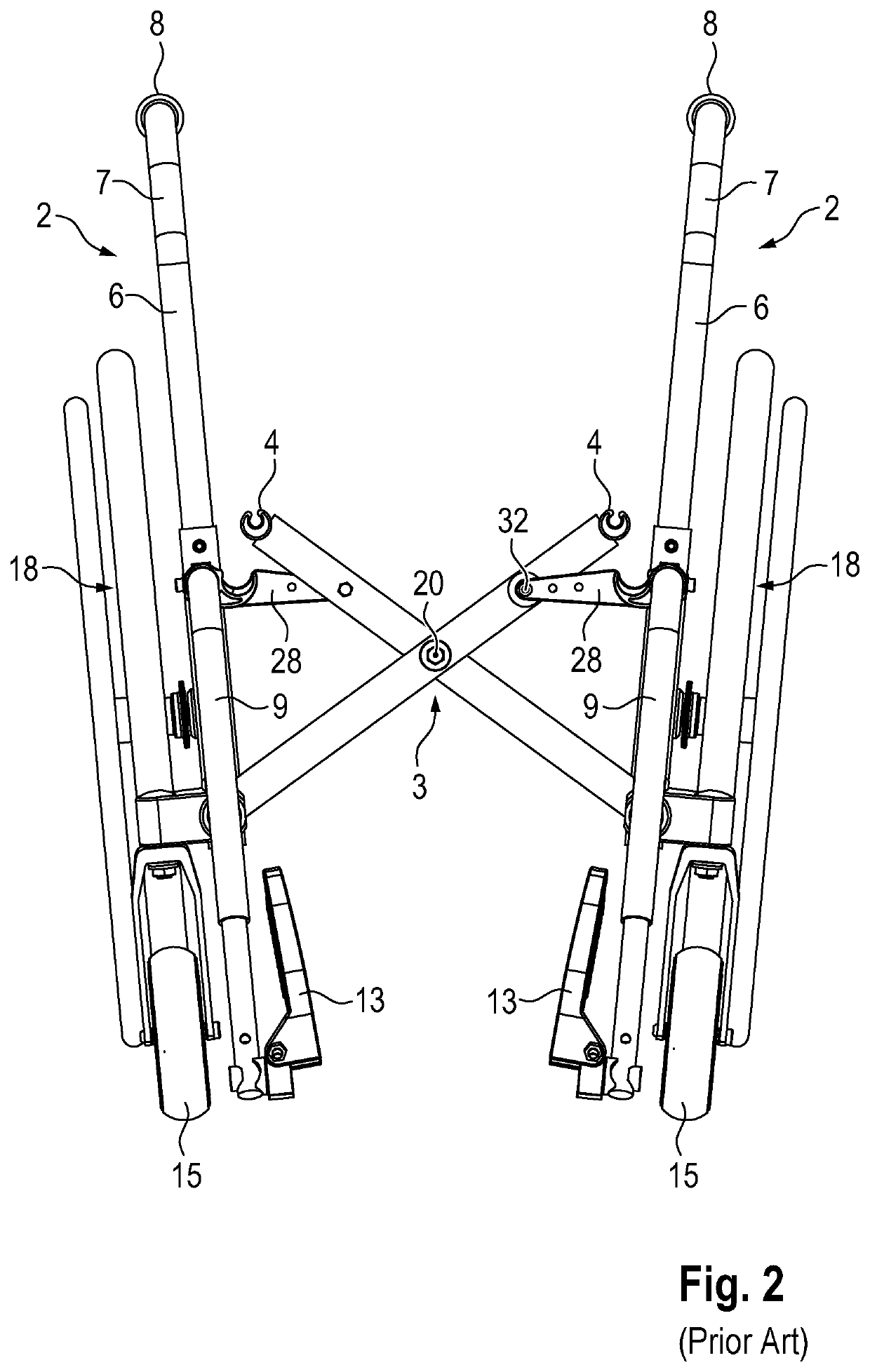
Thus, in this early phase of the folding process, the back tubes of the wheelchair move away from one another and generate a high tension on the back cover of the wheelchair if the latter does not have a correspondingly large degree of slack in the unfolded state of the wheelchair.
The latter possibility is not applicable to modern, energy-efficient wheelchairs, because such a wheelchair must be as rigid as possible and must have the least possible play in its articulated connections.
Furthermore, these methods of the combination thereof can only partially prevent the state effect.

Method used


Image

  • Folding wheelchair
  • Folding wheelchair
  • Folding wheelchair

Examples


Embodiment Construction

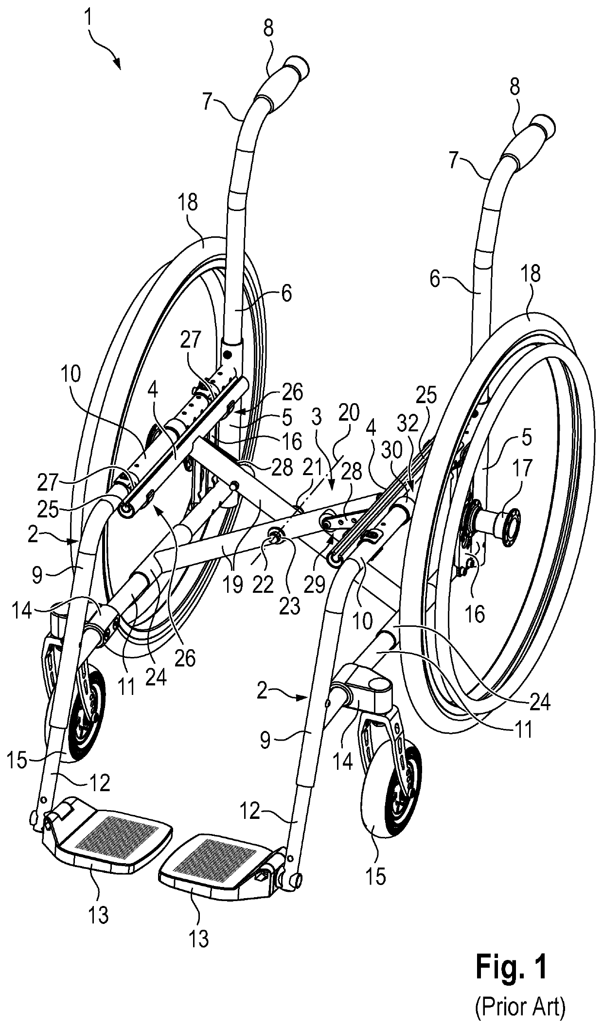
[0048]The following description relates firstly to the illustration of FIGS. 1 and 3, which relate to features which, in the foldable wheelchair 1 according to the prior art as per FIG. 1, are identical to those of the foldable wheelchair according to the present invention, that is to say as per FIG. 3. For a better overview of the kinematics of the parts of the wheelchair 1, the seat cover and the back cover have been omitted in the illustration of the wheelchair 1.

[0049]The foldable wheelchair 1 has side frames 2 arranged on both sides of the wheelchair 1, a cross-strut assembly 3, and seat tubes 4 for holding a seat cover. When the wheelchair 1 is fully unfolded, the seat cover mounted in the two parallel seat tubes 4 is tensioned.

[0050]The respective one of the two side frames 2 of Mirror-symmetrical identical form is formed as a frame formed from individual tubes. A rear tube 5 of the respective side frame 2 receives a height-adjustable tube 6, which is arranged substantially v...


PUM


Abstract

A foldable wheelchair having side frames arranged on both sides of the wheelchair, a cross-strut assembly and seat tubes for receiving a seat cover, wherein the cross-strut assembly is mounted about parallel pivot axes in the side frames, and an axis of rotation of struts of the cross-strut assembly is arranged parallel to the pivot axes of the cross-strut assembly, and the cross-strut assembly is connected to the seat tubes, wherein the wheelchair has guide levers and each guide lever is mounted in the respective strut of the cross-strut assembly between the axis of rotation of the struts of the cross-strut assembly and the respective seat tube, and the guide lever is mounted at a distance therefrom in the side frame assigned to the seat tube so as to be pivotable about a pivot axis that is arranged parallel to the pivot axes of the cross-strut assembly.

Description

CROSS REFERENCE TO RELATED APPLICATIONS[0001]This application is the United States national stage application of International Application No. PCT / EP2016 / 063134 filed on Jun. 9, 2016, which claims priority to European Application No. 15173451.4 filed on Jun. 23, 2015, the entire disclosures of which are incorporated herein by reference.BACKGROUND OF THE INVENTION AND RELATED ART[0002]The invention relates to a foldable wheelchair having side frames arranged on both sides of the wheelchair, a cross-strut assembly and seat tubes for receiving a seat cover, wherein the cross-strut assembly is mounted, in regions remote from the seat tube, about parallel pivot axes in the side frame, and the axis of rotation of the struts of the cross-strut assembly is arranged parallel to these pivot axes of the cross-strut assembly, and the cross-strut assembly is connected to the seat tubes, which, in the unfolded position of the wheelchair, are received by seat tube bearings of the side frames, wher...

Claims


Application Information

Patent Timeline
Patent Type & Authority Patents(United States)
IPC IPC(8): A61G5/08A61G5/10A61G5/12
CPCA61G5/1062A61G5/1054A61G5/08A61G5/0825A61G5/0883A61G5/128
Inventor HORACEK, GREGOR
Owner HORACEK GREGOR
Learn More