Lighting system with wireless power supply

a wireless power supply and wireless power supply technology, applied in the direction of electrical equipment, electric vehicles, lighting and heating apparatus, etc., can solve the problems of insufficient flexibility of previously known wireless power supply systems, limited applicability of inductive wireless power transfer, etc., and achieve the effect of a higher degree of flexibility in positioning

Active Publication Date: 2020-06-09
LEDVANCE GMBH
View PDF4 Cites 1 Cited by
  • Summary
  • Abstract
  • Description
  • Claims
  • Application Information

AI Technical Summary

Benefits of technology

[0007]In view of the known prior art, it is an object of the present invention to provide a lighting system allowing a much higher degree of flexibility in positioning.
[0014]The secondary luminaire can, thus, be used as portable lighting, for example as cabinet light, night light, flashlight and atmosphere light (mood light). Accordingly, the lighting system according to the present invention provides more flexibility in choosing a desired lighting scenario than previously known systems.
[0018]Using an RF wireless power transfer system further increases the flexibility for positioning the luminaires of the lighting system according to the present invention. Since electrical power can be transmitted by the RF wireless power transmitter to the primary luminaire as well as the secondary luminaire, both luminaires can be placed free from restrictions such as mains outlet position, cable length, relative position of induction coils, etc. present in the prior art.

Problems solved by technology

Inductive wireless power transfer is limited in its applicability in that the coils of transmitter and receiver must be aligned with respect to each other.
Previously known wireless power supply systems, however, lack the flexibility desired by many users.

Method used


Image

  • Lighting system with wireless power supply
  • Lighting system with wireless power supply
  • Lighting system with wireless power supply

Examples


first embodiment

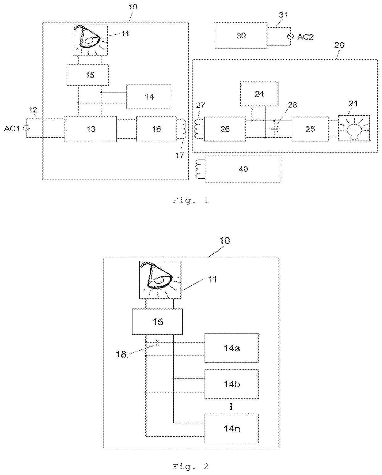
[0048]FIG. 2 shows a schematic view of the RF wireless power transfer part of the primary luminaire 10 that allows more than 2 W of electrical power to be transmitted via RF wireless power transfer. Other parts of the primary luminaire 10 are not shown in this drawing, but can of course still be present.

[0049]The RF wireless power receiver comprises multiple RF wireless power receiver units 14a, 14b, . . . , 14n. Each of the RF wireless power receiver units 14a, 14b, . . . , 14n can receive up to 2 W of electrical power. The power received by the RF wireless power receiver units 14a, 14b, . . . , 14n can be stored in an energy storage unit 18 (here shown as a capacitor) to which the RF wireless power receiver units 14a, 14b, . . . , 14n are connected in parallel. The luminaire 10 further comprises a DC current converter 15 for converting the current provided by the energy storage unit 18 into a current suitable for operating the light source 11. While any number of RF wireless power...

second embodiment

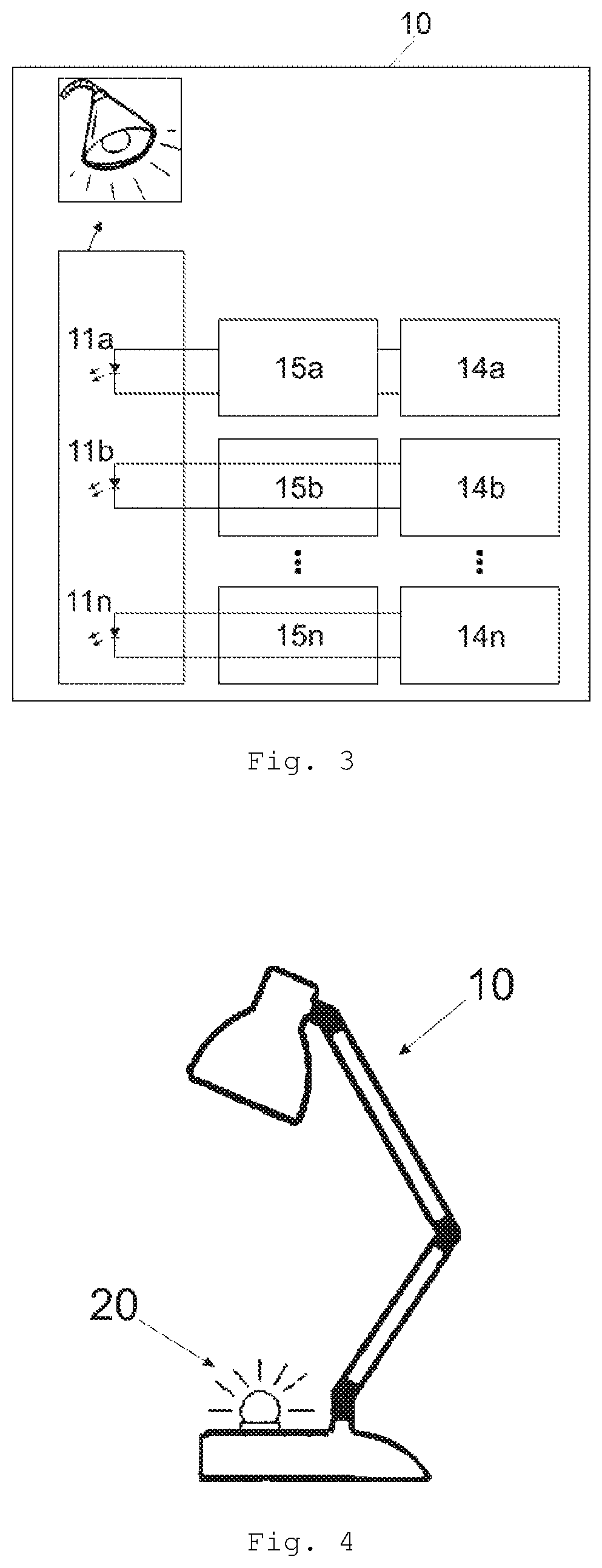
[0050]FIG. 3 shows a schematic view of the RF wireless power transfer part of the primary luminaire 10 that allows more than 2 W of electrical power to be transmitted via RF wireless power transfer. Other parts of the primary luminaire 10 are not shown in this drawing, but can of course still be present.

[0051]The RF wireless power receiver in this embodiment comprises multiple RF wireless power receiver units 14a, 14b, . . . , 14n. Each of the RF wireless power receiver units 14a, 14b, . . . , 14n can receive up to 2 W of electrical power. Each RF wireless power receiver unit 14a, 14b, . . . , 14n is connected to an associated DC current converter 15a, 15b, . . . , 15n which, in turn, is connected to an associated light source 11a, 11b, . . . , 11n. The output current of each RF wireless power receiver unit 14a, 14b, . . . , 14n is converted by the respective DC current converter 15a, 15b, . . . , 15n into a current suitable for operating the respective light source 11a, 11b, . . . ...


PUM


Abstract

A lighting system comprises a primary luminaire and a secondary luminaire each having a light source. Electrical power can be transmitted wirelessly via an inductive wireless power transmission from the primary to the secondary luminaire. Electrical power can also be transmitted wirelessly via an RF wireless power transmission from a RF wireless power transmitter to both luminaires. Energy can be stored in energy storage means. Thus, true wireless lighting can be achieved.

Description

CROSS-REFERENCE TO RELATED APPLICATIONS AND PRIORITY[0001]This patent application claims the benefit of and priority to Chinese Patent Application No. 2017100848457 filed on Feb. 16, 2017, the entire disclosure of which is incorporated herein by reference.Technical Field[0002]The present invention relates to a lighting system using wireless power supply. In particular, the invention relates to a lighting system having two luminaires, wherein electrical power can be transmitted from one luminaire to the other.Background[0003]Wireless charging of electronic devices is in particular known for smartphones and other small electronic devices which either include an inductive wireless power receiver or can be attached to such a receiver. When such a device is positioned on a corresponding inductive wireless power transmitter, electrical power is wirelessly transferred from the inductive wireless power transmitter to inductive wireless power receiver and used to charge and / or operate the de...

Claims


Application Information

Patent Timeline
Patent Type & Authority Patents(United States)
IPC IPC(8): F21L4/08H02J7/00F21S6/00H02J50/40H02J7/02H02J50/20H05B45/37H02J50/10H05B44/00
CPCH02J7/0013F21L4/08H05B45/37F21S6/002H02J50/40H02J50/20H02J50/10H02J5/005H05B45/3725
Inventor CHEN, SHAOPINGNIE, SHIJUNXIN, FAN
Owner LEDVANCE GMBH
Why Eureka
Try Eureka