Method for activating a function of a motor vehicle

a technology for motor vehicles and functions, applied in the field of motor vehicles, can solve the problems of loss of radiated power in the direction of the user's body, errors in detection, human body may have a negative impact on the performance of the antenna of the equipment, etc., and achieve the effect of reducing the effect of the loss of signal strength of the antenna, improving precision, and simple and reliable

Active Publication Date: 2020-06-16
CONTINENTAL AUTOMOTIVE FRANCE +1
View PDF5 Cites 2 Cited by
  • Summary
  • Abstract
  • Description
  • Claims
  • Application Information

AI Technical Summary

Benefits of technology

[0009]An aspect of the invention seeks to at least partially overcome these disadvantages by proposing a simple, reliable and effective solution for reducing the effects of the loss of signal strength of an antenna of a piece of user equipment caused by the body of said user so as to improve the precision with which the presence of the user in the detection zone around a motor vehicle is detected.
[0016]The method according to an aspect of the invention advantageously makes it possible to compensate for the RSSI value of a signal that is attenuated by the human body according to the position of the user equipment so as to determine precisely the distance separating said user equipment from the vehicle.
[0028]In this first embodiment, the user equipment constantly determines its position so that when it receives an advertising message it can quickly and precisely calculate the compensated value of the signal strength, estimate the distance separating it from the vehicle and send this distance to the vehicle.
[0046]In this third embodiment, the user equipment constantly determines its position so that when it receives an advertising message it can quickly and precisely calculate the compensated value of the signal strength, estimate the distance separating it from the vehicle and send a command message to the vehicle in order to activate one or more functions.
[0063]In this fifth embodiment, the vehicle determines the distance and detects the user equipment, making it possible to simplify the design of the user equipment by comparison with the previous embodiments.

Problems solved by technology

However, it is found that the human body may have a negative impact on the performance of the antenna of the equipment, depending on where it is located in relation to the human body.
Specifically, the tissues of the human body may absorb part of the radio signals emitted or received by the antenna of the user equipment, and cause a mismatch in the impedance of the antenna, thus leading to a loss in radiated power in the direction of the body of the user, which may for example be as much as 25 dB.
The loss of signal strength brought about by the position of the user equipment on the body reduces the RSSI value measured by the user equipment and sent to the vehicle, such that the distance values estimated may be erroneous, thus leading to errors in the detection of the presence of the user in the detection zone, something which therefore represents a major disadvantage.

Method used


Image

  • Method for activating a function of a motor vehicle
  • Method for activating a function of a motor vehicle
  • Method for activating a function of a motor vehicle

Examples


first embodiment

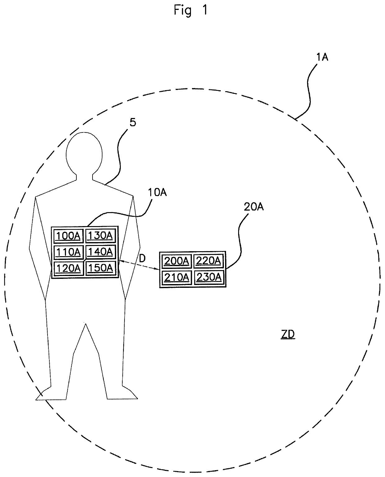
[0107]In the system 1A according to an aspect of the invention, illustrated in FIG. 1, the user equipment 10A comprises a position-determining module 100A, a receiving module 110A, a measurement module 120A, a calculation module 130A, an estimating module 140A and a sending module 150A.

[0108]The position-determining module 100A is configured for determining the position of the user equipment 10A with respect to the body of the user 5. Two examples of a position-determining module 100A will be presented.

[0109]In a first example, the user equipment 10A comprises at least one inertial sensor of accelerometer type which makes it possible to determine a signature of the position of the user equipment 10A in the three dimensions of space, as described hereinafter. By way of example, a 3-D accelerometer may be set to a specific sampling value, for example to a period of 20 ms, in order to identify the axis of orientation of the user equipment 10A by detecting the gravity (of the order of 9...

second embodiment

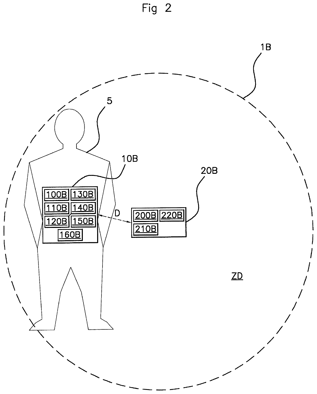
[0123]In the system 1B, illustrated in FIG. 2, the user equipment 10B comprises a position-determining module 100B, a receiving module 110B, a measurement module 120B, a calculation module 130B, an estimating module 140A, a presence-determining module 150B and a sending module 160B.

[0124]The position-determining module 100B is configured for determining the position of the user equipment 10B with respect to the body of the user 5. Two examples of a position-determining module 100B will be described.

[0125]In a first example, the user equipment 10B is made up of at least one inertial sensor of accelerometer type which makes it possible to determine a signature of the position of the user equipment 10B in the three dimensions of space, as described hereinafter. By way of example, a 3-D accelerometer may be set to a specific sampling value, for example to a period of 20 ms, used to identify the axis of orientation of the user equipment 10B by detecting the gravity (of the order of 9.8 m...

third embodiment

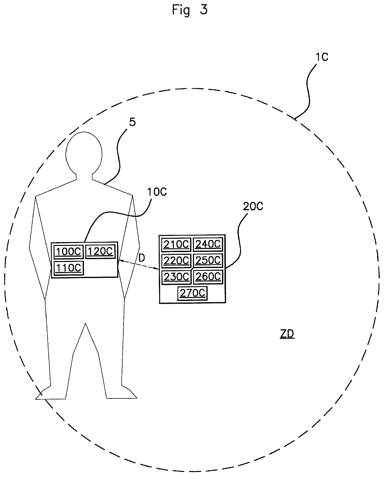
[0139]In the system 1C, illustrated in FIG. 3, the user equipment 10C comprises a receiving module 100C, a measurement module 110C, and a sending module 120C.

[0140]The receiving module 100C is configured for receiving a signal, sent by the vehicle 20C, containing an advertising message.

[0141]The measurement module 110C is configured for measuring the strength of a signal received by the receiving module 100C and for taking gyroscopic angle and / or acceleration measurements. For that purpose, the user equipment 10C may comprise at least one accelerometer and one gyroscope which will make it possible to determine a signature of the position of the user equipment 10C in the three dimensions of space, as described hereinafter. By way of example, a 3-D accelerometer may be used to identify the axis of orientation of the user equipment 10C by detecting the gravity (of the order of 10 m / s2) on one of the three axes. In other words, the orientation of the user equipment 10C is determined by ...


PUM


Abstract

A method for activating a function of a motor vehicle upon detecting the presence of a user apparatus in a predetermined detection area around the vehicle. The method includes a step of determining the position of the user apparatus relative to the body of the user; a step of receiving, by the user apparatus, a signal comprising a broadcast message sent by the vehicle; a step of calculating a compensated value of the power of the signal received from the determined position of the user apparatus; a step of estimating the distance separating the user apparatus from the vehicle using the compensated power value, and a step of activating at least one function by the vehicle when the estimated distance is less than a predetermined threshold.

Description

CROSS REFERENCE TO RELATED APPLICATIONS[0001]This application is the U.S. National Phase Application of PCT International Application No. PCT / EP2016 / 001930, filed Nov. 18, 2016, which claims priority of French Application No. FR 1561607, filed Nov. 30, 2015, the contents of such applications being incorporated by reference herein.FIELD OF THE INVENTION[0002]The present invention relates to the field of motor vehicles and more particularly covers a method for activating a function of a motor vehicle following detection of the presence of user equipment in a predetermined detection zone around said vehicle.BACKGROUND OF THE INVENTION[0003]Nowadays, certain motor vehicles are able to communicate with equipment carried or worn by the users of these vehicles, such as an electronic ignition key or a smart phone.[0004]Communication between a vehicle and such user equipment makes it possible for example to detect the presence of the user in a predetermined detection zone around the vehicle ...

Claims


Application Information

Patent Timeline
Patent Type & Authority Patents(United States)
IPC IPC(8): H04B17/00H04B17/27B60R25/31G07C9/00H04B17/318B60R25/24
CPCH04B17/27G07C9/00309B60R25/31H04B17/318B60R25/245G07C2009/00507G07C2209/63
Inventor GODET, SYLVAIN
Owner CONTINENTAL AUTOMOTIVE FRANCE
Why Eureka
Try Eureka