Borehold testing device

a testing device and borehold technology, applied in the direction of borehole/well accessories, instruments, surveys, etc., can solve the problems of inability to achieve the effect of improving efficiency, reducing the time required for testing, and inability to achieve the effect of increasing the settlement of the supported structur

Active Publication Date: 2020-06-23
PILE DYNAMICS
View PDF98 Cites 1 Cited by
  • Summary
  • Abstract
  • Description
  • Claims
  • Application Information

AI Technical Summary

Benefits of technology

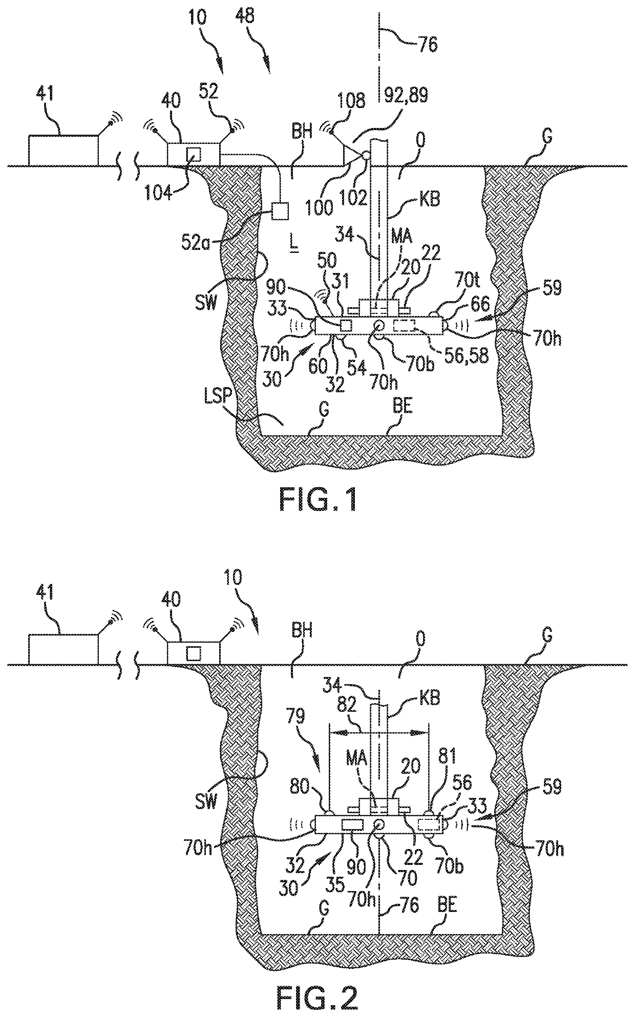
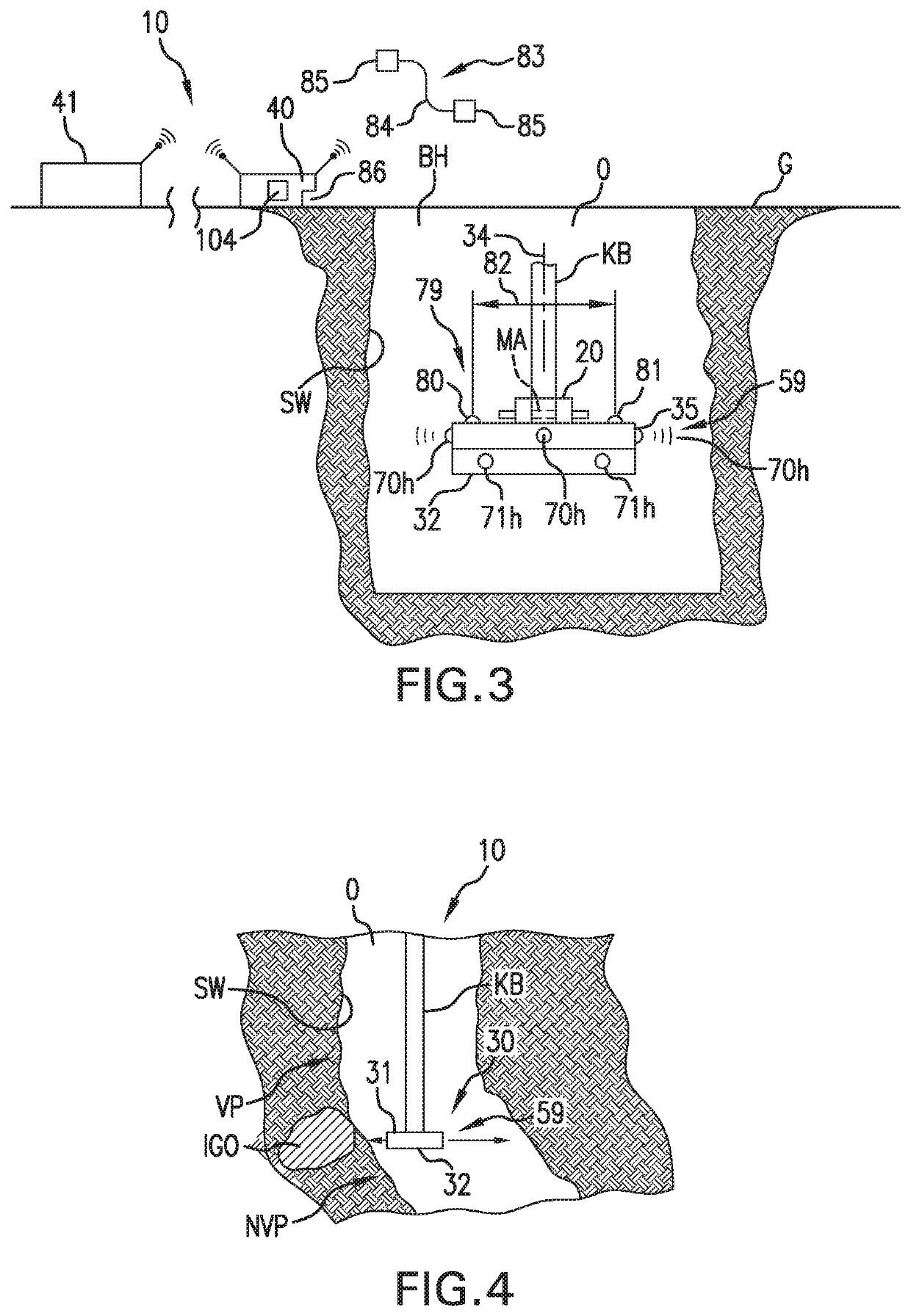
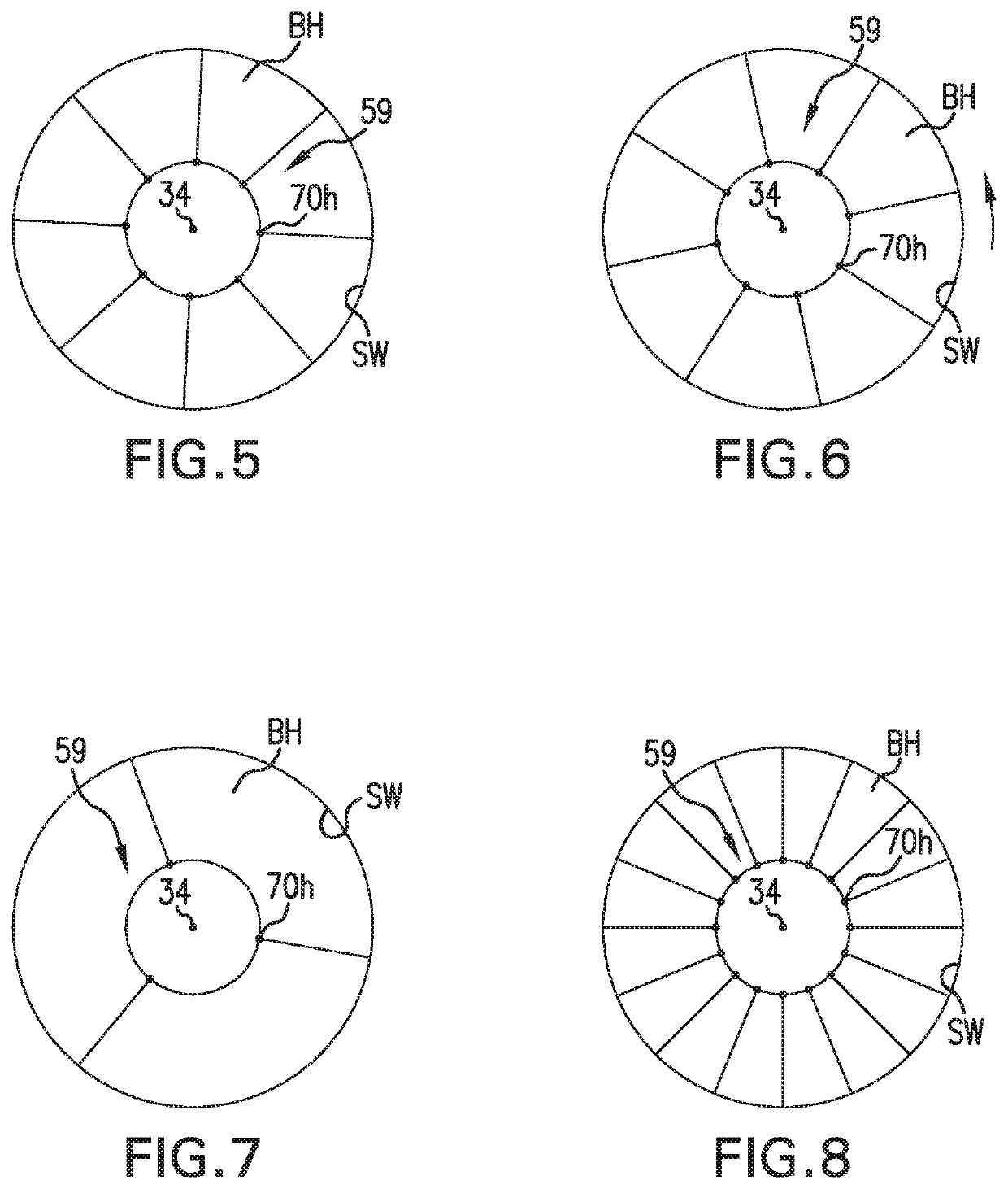
[0014]Even more particularly, the invention of this application relates to a borehole inspection device or system that has a configuration that allows it to be operated “wirelessly” as is defined by the application, but this is not required. Yet further, it can quickly and accurately measure the condition of the borehole including, but not limited to, accurately measure and / or determine the configuration of the bottom and / or side wall(s) of the opening or excavation to provide fast and reliable information about the quality, shape, radius and / or verticality of the borehole and / or excavation.
[0037]According to yet other aspects of the present invention, the system can include the sensing on the head unit that is lowered into the borehole and a surface system (on site or off site) that can be in communication with the head unit and that can display real time data viewable by the operator of the device, personnel on site and / or personnel off site thereby preventing the system from being removed from the borehole for each location tested on the borehole bottom, thus improving efficiency and reducing the time required for testing.

Problems solved by technology

Loose soil also contributes to undesirable increased settlement of the supported structure.
The success of the bottom cleaning is, however, not assured and several passes or cycles of this effort may be needed.
The uncertainty can lead to unnecessary effort and, therefore, cost.

Method used


Image

  • Borehold testing device
  • Borehold testing device
  • Borehold testing device

Examples


Embodiment Construction

[0050]Referring now to the drawings wherein the showings are for the purpose of illustrating preferred and alternative embodiments of the invention only and not for the purpose of limiting the same, shown is a borehole inspection device or system 10 that includes one or more components that are mountable, fixed relative to and / or mounted to a lowering device, such as a Kelly Bar KB or a lowering cable. In this respect, while the invention of this application is being described in connection with a Kelly Bar, the inspection device can connected to any equipment or system used to excavate, bore, lower and / or inspect the opening including, but not limited to, being mountable to a Kelly Bar, a main cable line, main chain line, excavation and / or boring equipment, and / or any other lowering device known in the industry that is used to dig, excavate, bore, lower and / or clean out the borehole and / or excavation. Therefore, while the invention is being described for use in connection with a Ke...


PUM


Abstract

An inspection system to measure the condition of at least a wall of a ground opening, the inspection system having a head unit for lowering into a borehole during a data collection phase wherein at least one set of test data is collected concerning one or more physical characteristics of the borehole during the data collection phase, the head unit having an internal measurement system and a sensor arrangement with a plurality of sensors facing radially outwardly of a head axis that is generally parallel to at least a portion of a borehole axis, the plurality of sensors allowing the head unit to be moved during the data collection phase without rotation about the head axis, the plurality of sensors at least partially producing the at least one set of test data collected during the data collection phase.

Description

[0001]This application is a continuation of patent application Ser. No. 15 / 233,317 that was filed on Aug. 10, 2016, which claims priority in Provisional Patent Application Ser. No. 62 / 205,335, filed on Aug. 14, 2015. In addition, patent application Ser. No. 15 / 233,317 is a Continuation-in-Part application of U.S. patent application Ser. No. 14 / 560,879 that was filed on Dec. 4, 2014, which claims the benefit of Provisional Application Ser. No. 61 / 912,206 that was filed on Dec. 5, 2013. All of these prior filings are incorporated by reference herein.[0002]The invention of this application relates to a measuring device that can be deployed in a borehole or any deep excavation or opening to inspect the borehole and / or excavation, in particular, to inspect the bottom and / or side walls of the excavation and provide fast and reliable information about the quality, shape and / or verticality of the borehole and / or excavation.INCORPORATION BY REFERENCE[0003]McVay et al.—U.S. Pat. No. 6,533,502...

Claims


Application Information

Patent Timeline
Patent Type & Authority Patents(United States)
IPC IPC(8): G01V11/00E21B47/08E02D1/02E21B47/00G01V9/00
CPCE21B47/002E21B47/00G01V9/00E21B47/085E02D1/02G01V11/002E21B47/0025
Inventor PISCSALKO, GEORGE R.COTTON, DEAN A.BERRIS, JR., RICHARD E.PIEDIMONTE, TYLER A.
Owner PILE DYNAMICS
Why Eureka
Try Eureka