
Bumper protection apparatus

a bumper protection and bumper technology, applied in the direction of bumpers, mechanical equipment, transportation and packaging, etc., can solve the problems of affecting the safety of passengers, so as to minimize the damage to the other vehicle and minimize corrosion or degradation.

Active Publication Date: 2020-06-30
SEVILLE MEDICAL INC
View PDF7 Cites 0 Cited by
  • Summary
  • Abstract
  • Description
  • Claims
  • Application Information

AI Technical Summary

Benefits of technology

The patent describes a device that can protect a vehicle from damage caused by impacts with other vehicles. The device includes a cover that conceals the head portion of a fastener with an anchor body, which prevents the fastener from coming into contact with other vehicles. The cover also protects the fastener from elements and debris, which can cause corrosion or degradation of the fastener. Overall, the device helps to minimize damage to the vehicle and ensures its safety.

Problems solved by technology

When parallel parking it is not uncommon to tap the parked vehicle in front or behind, and those seemingly innocuous light taps cause the exposed screw heads to come into contact with the bumpers of the parked vehicles, resulting in scratches, scuffs and dents.
Also, when driving in bumper to bumper traffic conditions the damage caused by tapping another vehicle's bumper is magnified.
Fixing damaged bumpers involves grinding, sanding, sculpting and painting, which can be costly, time consuming, and can often exceed the insurance deductible for certain vehicles.
In addition, for a typical driver the likelihood of such taps is extremely high, and can occur each time one parallel parks or drives in bumper to bumper traffic, and therefore these repair costs may become prohibitive, and often forces some drivers forego repairs and maintain the damaged bumpers in their unsightly states.
Furthermore, since the screw heads are exposed to exposure to rain, snow or road salt, they are susceptible to corrosion or rust.
Rusted screws may be difficult to remove, and may require to be drilled out of the bumper by a mechanic in order to access the plate, which can be costly and inconvenient.

Method used


Image

  • Bumper protection apparatus
  • Bumper protection apparatus
  • Bumper protection apparatus

Examples


Embodiment Construction

[0038]The detailed description of exemplary embodiments of the invention herein makes reference to the accompanying block diagrams and schematic diagrams, which show the exemplary embodiment by way of illustration. While these exemplary embodiments are described in sufficient detail to enable those skilled in the art to practice the invention, it should be understood that other embodiments may be realized and that logical and mechanical changes may be made without departing from the spirit and scope of the invention. Thus, the detailed description herein is presented for purposes of illustration only and not of limitation. For example, the steps recited in any of the method or process descriptions may be executed in any order and are not limited to the order presented.

[0039]Moreover, it should be appreciated that the particular implementations shown and described herein are illustrative of the invention and its best mode and are not intended to otherwise limit the scope of the prese...


PUM

PropertyMeasurementUnit
diameteraaaaaaaaaa
compressibleaaaaaaaaaa
forcesaaaaaaaaaa

Abstract

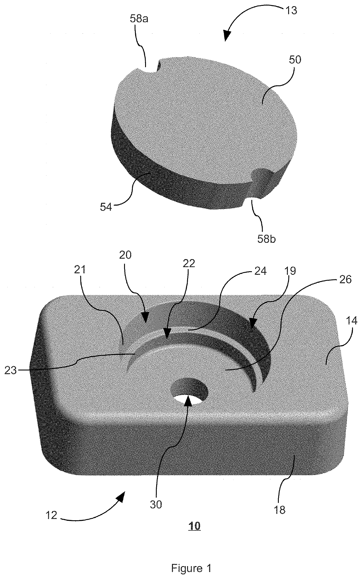
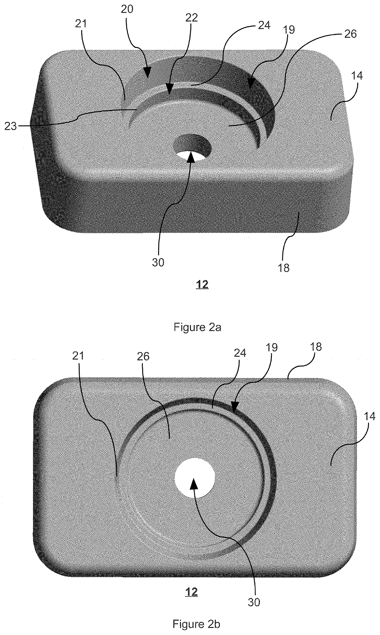
A bumper protection apparatus, the apparatus comprising: an anchor body having an exterior top wall, an exterior bottom wall, and an exterior side wall extending therebetween; the top wall comprising a top recessed annular section with top interior peripheral wall, and a bottom recessed annular section with bottom interior peripheral wall, and an annular shoulder separating the top interior peripheral wall and the bottom interior peripheral wall, to form a generally graduated cylindrical void bottom within the anchor body; a base wall formed with bottom interior peripheral wall, the base wall being opposite to exterior bottom wall; the base wall having an aperture extending therefrom to exterior bottom wall; and a cover comprising an exterior cover wall and an interior cover wall with an edge wall therebetween, the cover dimensioned to fit snugly in the anchor body within the top recessed annular section.

Description

CROSS-REFERENCE TO RELATED APPLICATIONS[0001]This application claims the benefit of priority to U.S. Provisional Application Ser. No. 62 / 487,803, filed on Apr. 20, 2017.FIELD OF THE INVENTION[0002]The present invention relates to a bumper protection apparatus, more particularly it pertains to a resilient fastener housing assembly for use with vehicle registration plates.BACKGROUND[0003]In most jurisdictions all roadworthy vehicles or trailers are required by law to be registered with an appropriate governmental for official identification purposes. Accordingly, such vehicles are assigned a unique registration identifier, which may be numeric and / or alphanumeric, that uniquely identifies the vehicle owner within the issuing region's database. The unique registration identifier is printed or embossed onto a vehicle registration plate which is affixed onto the vehicle or trailer, along with a plate renewal sticker that must be renewed and replaced periodically.[0004]Typically, the vehi...

Claims


Application Information

Patent Timeline
Patent Type & Authority Patents(United States)
IPC IPC(8): B60R19/50F16F1/36B60R13/10B60R19/44
CPCF16F1/36B60R13/105B60R19/50B60R19/44F16F2230/0023
Inventor KRENSKY, ROBERT
Owner SEVILLE MEDICAL INC
Learn More