Eureka AIR delivers breakthrough ideas for toughest innovation challenges, trusted by R&D personnel around the world.

Unmanned aerial vehicle

a technology for unmanned aerial vehicles and vehicles, applied in the field of aerial vehicles, can solve the problems of inertia of the proper weight distribution and achieve the effect of reducing the inertial moment of the unmanned aerial vehicle and shortening the signal path

Active Publication Date: 2020-07-07
UVIONIX AEROSPACE CORP
View PDF5 Cites 0 Cited by
  • Summary
  • Abstract
  • Description
  • Claims
  • Application Information

AI Technical Summary

Benefits of technology

[0008]It is another object of the present invention to provide an unmanned aerial vehicle in which the weight of the UAV is distributed in such a way as to minimize the inertial moment of the UAV.
[0009]It is another object of the present invention to provide an unmanned aerial vehicle that provides a shorter path for signal and / or power-carrying cables as compared to existing vehicles.
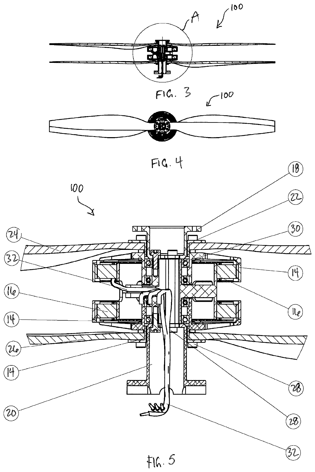
[0012]According to another embodiment of the present invention, a method for minimizing the inertial moment of an unmanned aerial vehicle includes providing a tubular base structure having a generally hollow interior, an upper end and a lower end, equipping the tubular base structure with a motor and at least one propeller configured to be driven by the motor, connecting a hollow compartment to one of the upper end of the tubular base structure and the lower end of the tubular base structure, and connecting an energy storage module to the tubular base structure, the energy storage module being configured to supply power or fuel to the motor. The tubular base structure houses at least one cable for routing power or signals, or a fuel conduit or wire conduit.

Problems solved by technology

One notable problem when designing single rotor or dual coaxial rotor UAVs is the inherent difficulty of the proper weight distribution throughout the UAV.

Method used


Image

  • Unmanned aerial vehicle
  • Unmanned aerial vehicle
  • Unmanned aerial vehicle

Examples


Embodiment Construction

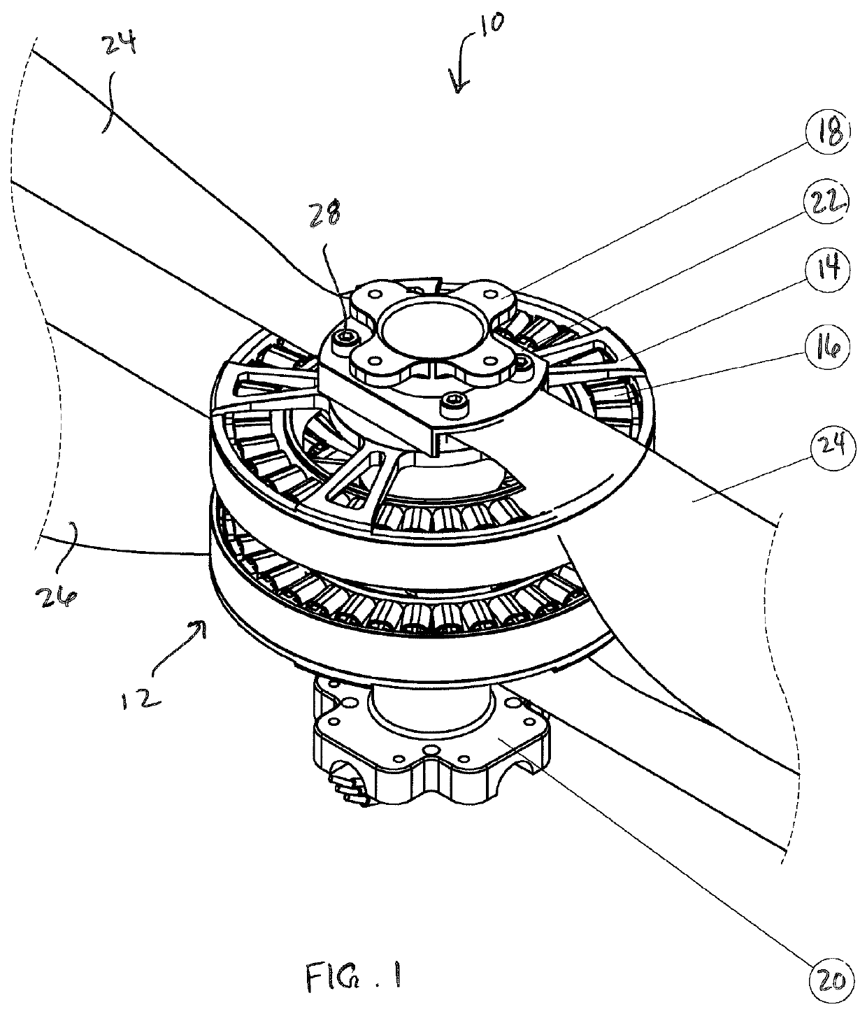
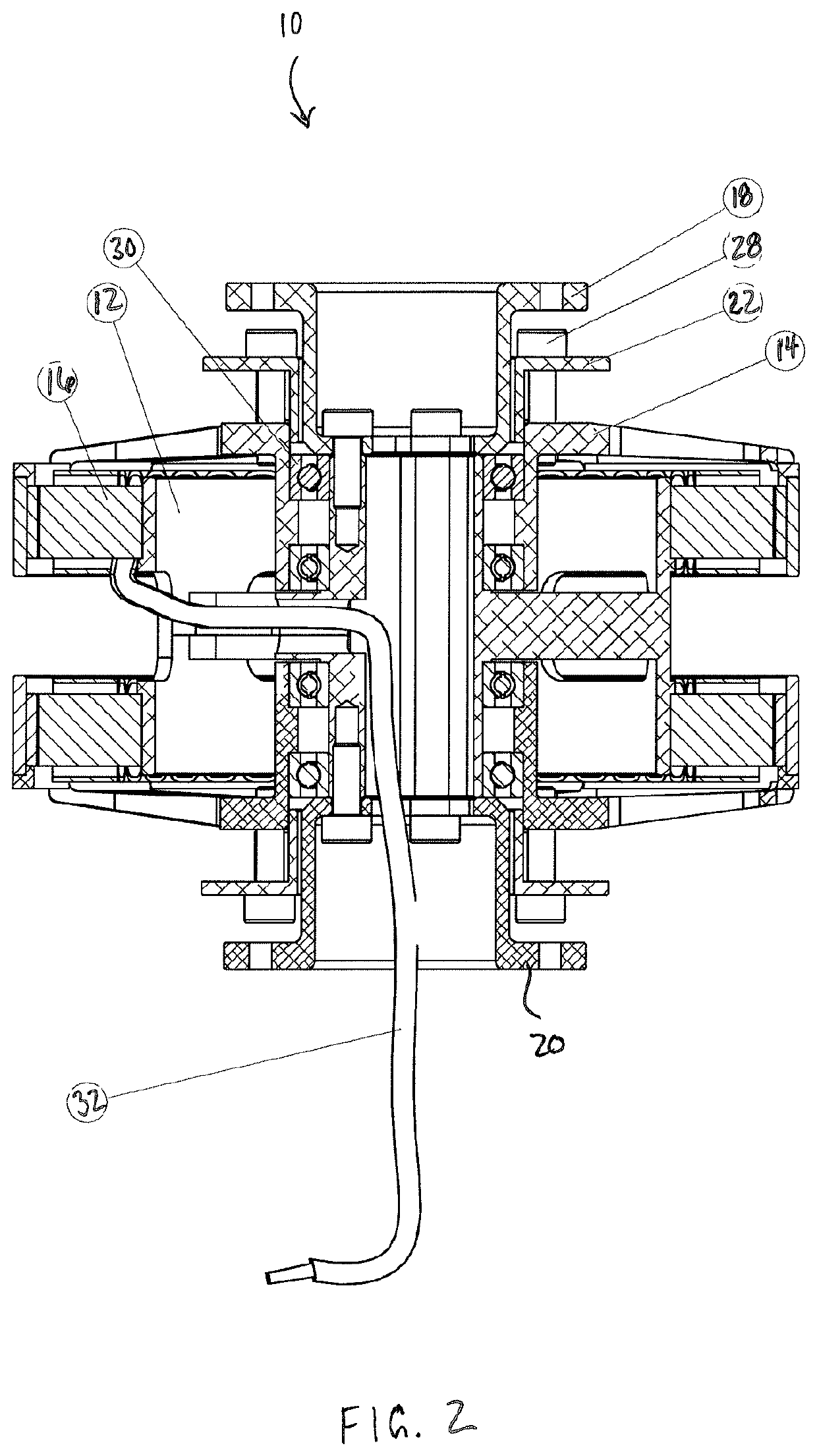
[0021]With reference to FIGS. 1 and 2, an unmanned aerial vehicle (“UAV”) 10 according to an embodiment of the present invention is illustrated. The UAV 10 may generally take the form of any UAV known in the art. As illustrated therein, the UAV is depicted as a dual coaxial rotor UAV. The UAV 10 includes a tubular base structure 12 operatively connected to a motor having a rotor 14 and a stator 16. As best illustrated in FIG. 2, the tubular base structure 12 is rigidly attached to the stator of the motor (or to the stators of both motors in the case of a dual coaxial rotor). In an embodiment, the stator(s) 16 and the tubular base structure 12 are integrated into a single structure.

[0022]The tubular base structure 12 preferably includes, or is otherwise connected to, an upper flange 18 and a lower flange 20 (or similar mounting fixtures), the purposes of which will be described hereinafter. The tubular base 12 also includes a rotor flange 22 connected to the rotor 14, which is utiliz...


PUM


Abstract

An unmanned aerial vehicle includes a tubular base structure, a motor having a stator, the stator being connected to the tubular base structure, an energy storage module configured to supply power to the motor, and at least one propeller driven by the motor, wherein the tubular base structure houses at least one cable for routing power or signals, or a fuel conduit or wire conduit.

Description

CROSS-REFERENCE TO RELATED APPLICATIONS[0001]This application claims the benefit of U.S. Provisional Application Ser. No. 62 / 327,014, filed on Apr. 25, 2016, which is hereby incorporated by reference herein in its entirety.FIELD OF THE INVENTION[0002]The present invention relates generally to aerial vehicles and, more particularly, to an unmanned aerial vehicle having a tubular base structure.BACKGROUND OF THE INVENTION[0003]An unmanned aerial vehicle (UAV), commonly known as a drone, is an aircraft without a human pilot aboard. Its flight is controlled either autonomously by onboard computers or by the remote control of a pilot on the ground or in another vehicle. UAVs are commonly used in military and special operations applications, and are increasingly finding uses in civil, commercial and recreational applications, such as policing and surveillance, aerial filming, and delivering of packages to end consumers.[0004]Existing UAVs may be of the single rotor or dual coaxial rotor t...

Claims


Application Information

Patent Timeline
Patent Type & Authority Patents(United States)
IPC IPC(8): B64C39/02
CPCB64C39/024B64C2201/162B64C2201/108B64U30/20B64U50/14B64U50/30B64U50/19
Inventor ISKREV, YORDANISKREV, BORIS
Owner UVIONIX AEROSPACE CORP
Why Eureka
Eureka Blog
Learn More