
Eureka
For R&D, Eureka makes reading and utilizing patents & technical documents easy.
Eureka AIR
Designed for self-driven R&D workflows. Generate viable solutions, solve complex R&D challenges, empower your innovation with AI.

Eureka Materials
Designed for material experts only. Revolutionize your material R&D, from search, analyze, to developing new materials.

TechResearch
Generate reliable direction feasibility study reports for your R&D in just a few steps.

TechSeek
Discover and master advanced knowledge NOW. Basics, ideas, possibilities, all at once.

TechMind
As an expert in R&D Theories, TechMind can generates customized viable solutions instantly.

TechRisk
Analyze your overall solution with one click, know your potential R&D risks in advance.

TechMonitor
Get weekly tech updates, stay abreast of the latest tech innovations and key insights.
Unmanned aerial vehicle
- Summary
- Abstract
- Description
- Claims
- Application Information
AI Technical Summary
Benefits of technology
Problems solved by technology
Method used
Image

Examples
Embodiment Construction
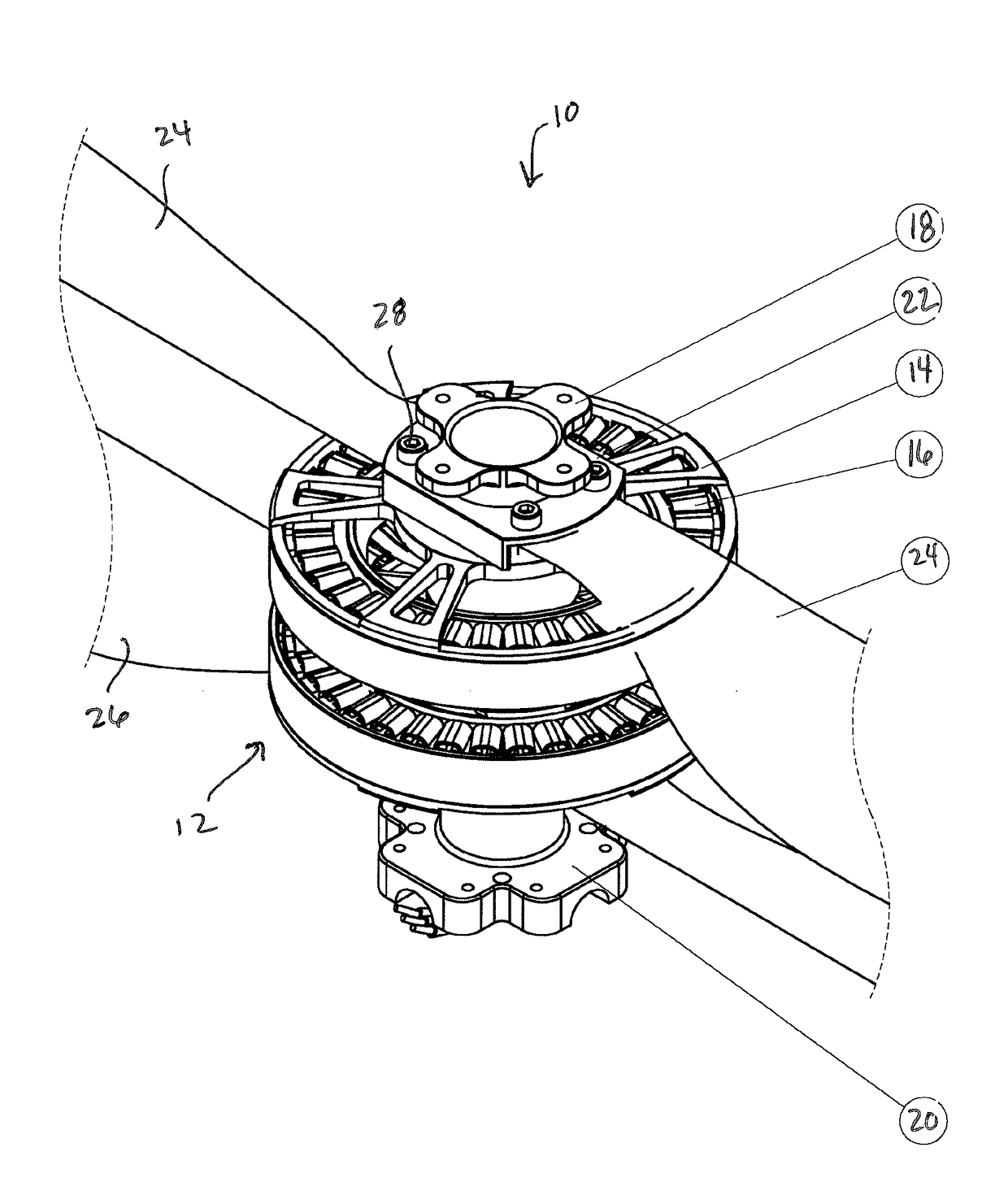
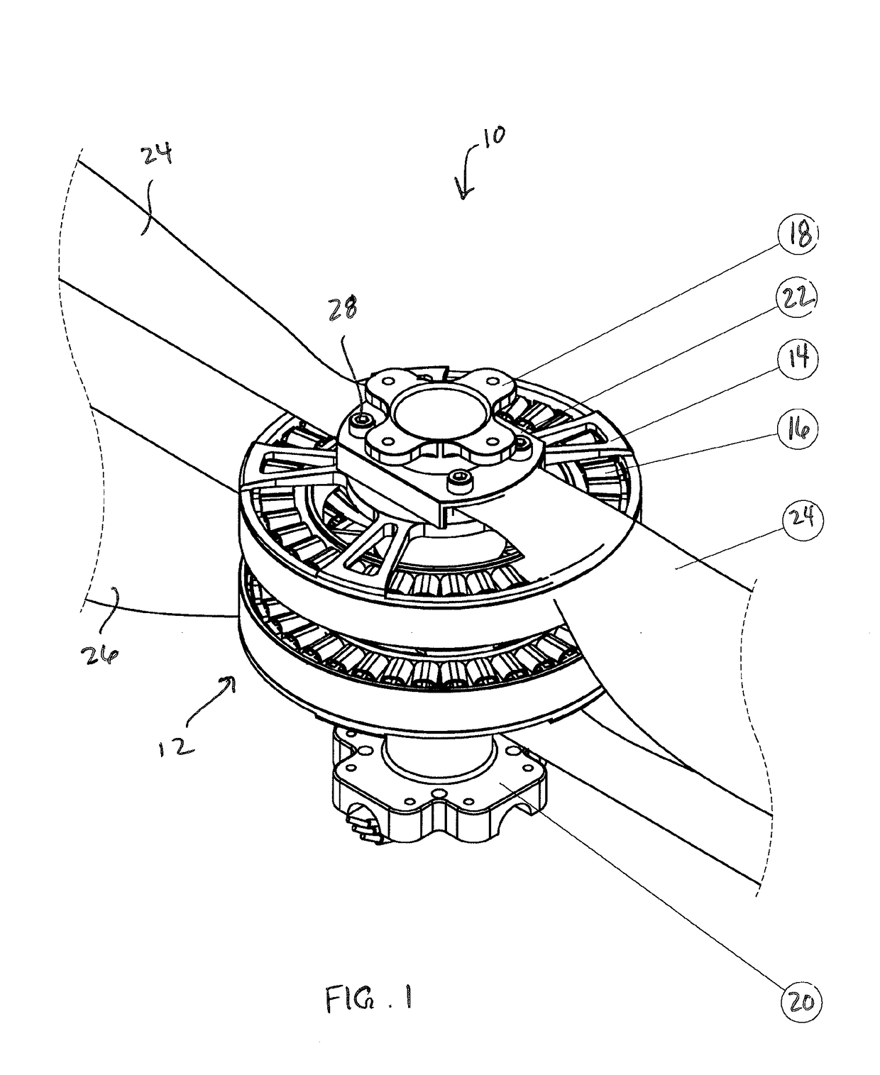
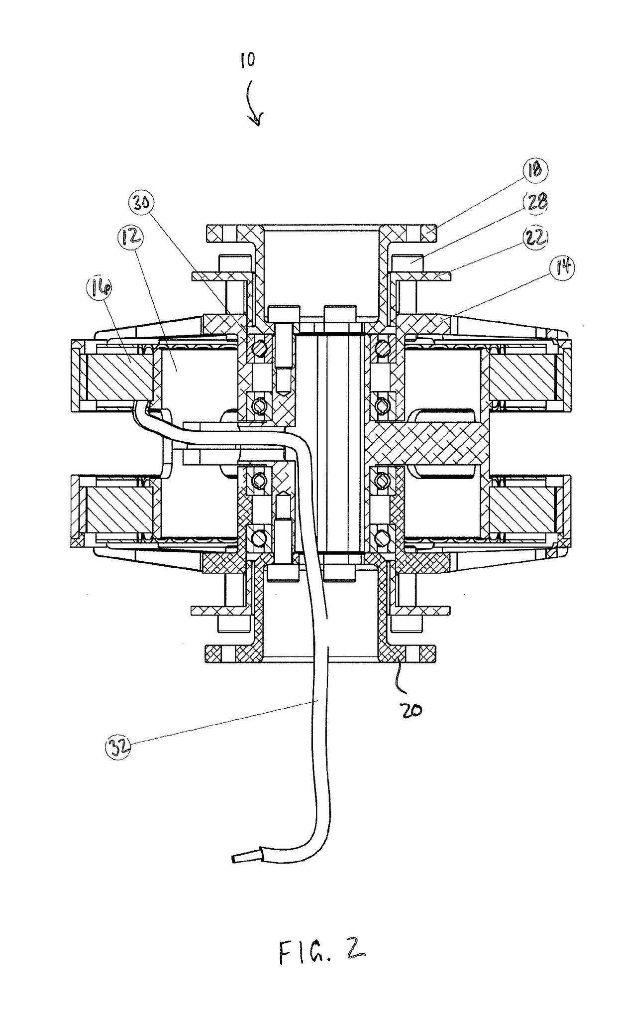
[0021]With reference to FIGS. 1 and 2, an unmanned aerial vehicle (“UAV”) 10 according to an embodiment of the present invention is illustrated. The UAV 10 may generally take the form of any UAV known in the art. As illustrated therein, the UAV is depicted as a dual coaxial rotor UAV. The UAV 10 includes a tubular base structure 12 operatively connected to a motor having a rotor 14 and a stator 16. As best illustrated in FIG. 2, the tubular base structure 12 is rigidly attached to the stator of the motor (or to the stators of both motors in the case of a dual coaxial rotor). In an embodiment, the stator(s) 16 and the tubular base structure 12 are integrated into a single structure.
[0022]The tubular base structure 12 preferably includes, or is otherwise connected to, an upper flange 18 and a lower flange 20 (or similar mounting fixtures), the purposes of which will be described hereinafter. The tubular base 12 also includes a rotor flange 22 connected to the rotor 14, which is utiliz...
PUM
 Abstract
Description
Claims
Application Information
 - R&D Engineer
- R&D Manager
- IP Professional
- Industry Leading Data Capabilities
- Powerful AI technology
- Patent DNA Extraction
Browse by: Latest US Patents, China's latest patents, Technical Efficacy Thesaurus, Application Domain, Technology Topic, Popular Technical Reports.
© 2024 PatSnap. All rights reserved.Legal|Privacy policy|Modern Slavery Act Transparency Statement|Sitemap|About US| Contact US: help@patsnap.com