

Solder preform
a preform and conductive technology, applied in the field of preforms, can solve the problems of power continuity or mechanical robustness, heat dissipation bottleneck to the subsequent cooling material stack, and it is difficult and sometimes impossible to realize a conductive solder interfacial layer with minimal voiding, so as to increase the effectiveness of oxygen purging, reduce gasses, and increase the effect of vacuum soldering
- Summary
- Abstract
- Description
- Claims
- Application Information
AI Technical Summary
Benefits of technology
Problems solved by technology
Method used
Image

Examples
Embodiment Construction
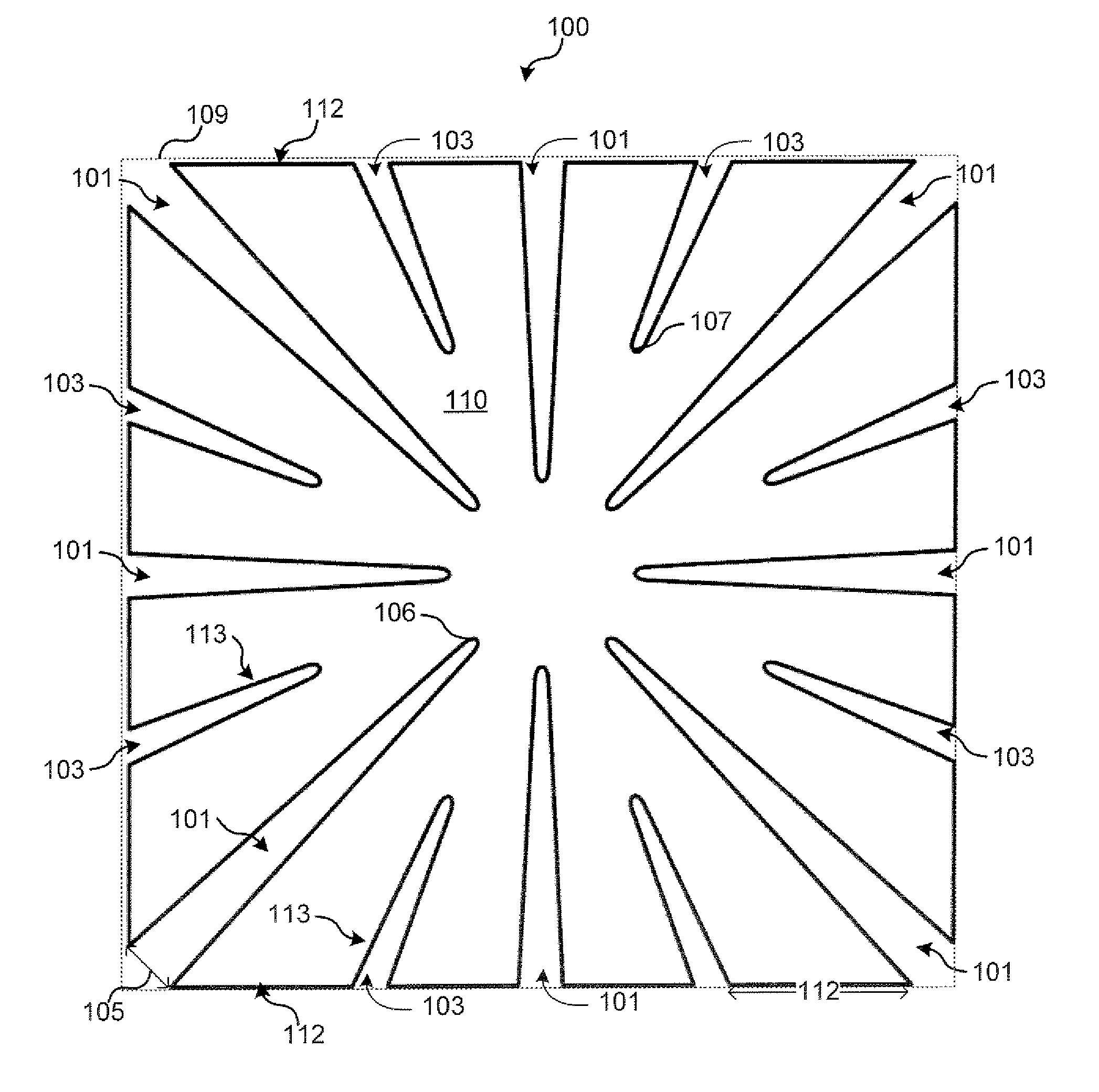
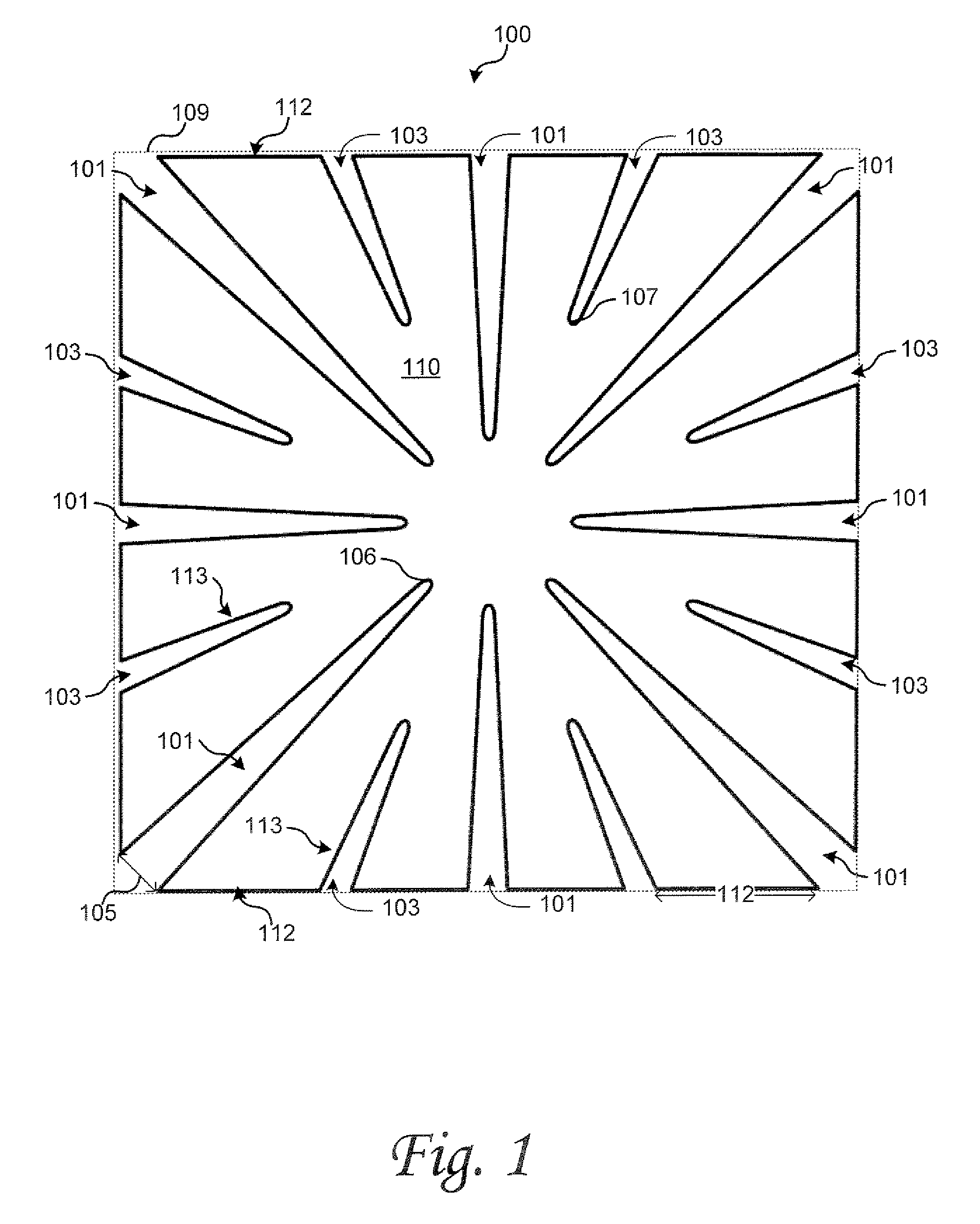
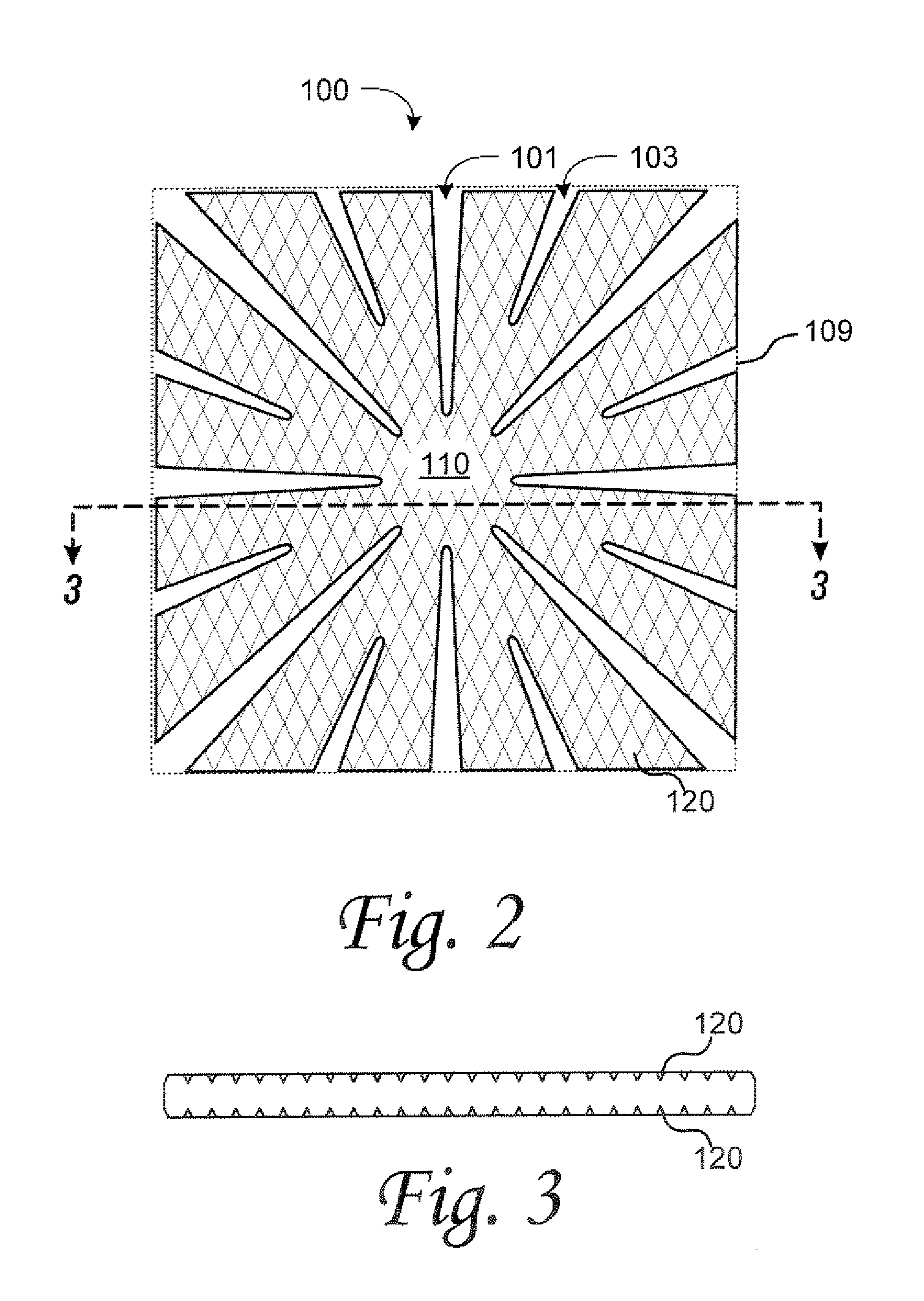
[0009]According to various embodiments of the invention, A solder preform has gaps extending from the boundary of the preform towards the preform center. During reflow soldering, the gaps close from the center towards the boundary. This allows flux and gasses to escape the interface between the solder and the substrate. Particularly, flux accumulates in the spaces formed by the gaps and is forced to the edge of the solder preform as the gap closes. In further embodiments, channels are formed on one or both surfaces of the solder preform. In addition to further assisting in the escape of gas and flux during reflow, the channels increase the effectiveness of oxygen purging using inert or reducing gasses in the reflow chamber. The channels also increase the effectiveness of vacuum soldering by increasing the preform's surface area. This creates shorter paths for embedded oxides to be pulled out from the solder area to the external surface.
[0010]According to an embodiment of the inventi...
PUM
| Property | Measurement | Unit |
|---|---|---|
| area | aaaaa | aaaaa |
| perimeter | aaaaa | aaaaa |
| volume | aaaaa | aaaaa |
Abstract
Description
Claims
Application Information