Fuel supply device

Active Publication Date: 2020-07-07
AISAN IND CO LTD
View PDF24 Cites 6 Cited by
  • Summary
  • Abstract
  • Description
  • Claims
  • Application Information

AI Technical Summary

Benefits of technology

[0008]The present disclosure is made in view of the above disadvantage, and it is an objective of the present disclosure to provide a fuel supply device that can limit a breakage at a radial support part of a coupling stay that provides radial support to a pump unit.
[0021]Here, according to the first aspect of the present disclosure, the boundary of the radial support part and the contact part between the lock projection and the support lateral surface are not likely displaced in the transverse direction along the rotational axis. Therefore, the fulcrum and the point of load may appear substantially along a common plane. Furthermore, according to the first aspect of the present disclosure, the height of the contact part between the lock projection and the support lateral surface is limited to the height that is equal to or lower than the rotational axis, so that the point of load may appear between the point of effort and the fulcrum in the longitudinal direction. Accordingly, the amount of displacement of the point of load about the fulcrum is reduced, and an urging force, which urges the rotatable shaft portion toward the pump unit side, becomes dominant at the point of load. Thereby, it is possible to limit the breakage of the rotatable shaft portion at the radial support part.
[0023]In the coupling stay according to the second aspect of the present disclosure, the radial support part is formed by the resilient support portion that has the another one of the rotatable shaft portion and the support inner peripheral surface and is resiliently deformable. Accordingly, a pulling force, which is applied to the rotatable shaft portion at the boundary of the radial support part, can be reduced by the resilient deformation of the resilient support portion. Thereby, it is possible to improve a breakage limiting effect for limiting the breakage of the rotatable shaft portion at the radial support part.

Problems solved by technology

The rotation of the pump unit relative to the coupling stay is used at the time of inserting the fuel supply device into the inside of the fuel tank and thereby needs to be limited by the locking after the insertion of the fuel supply device into the inside of the fuel tank.

Method used


Image

  • Fuel supply device
  • Fuel supply device
  • Fuel supply device

Examples


first embodiment

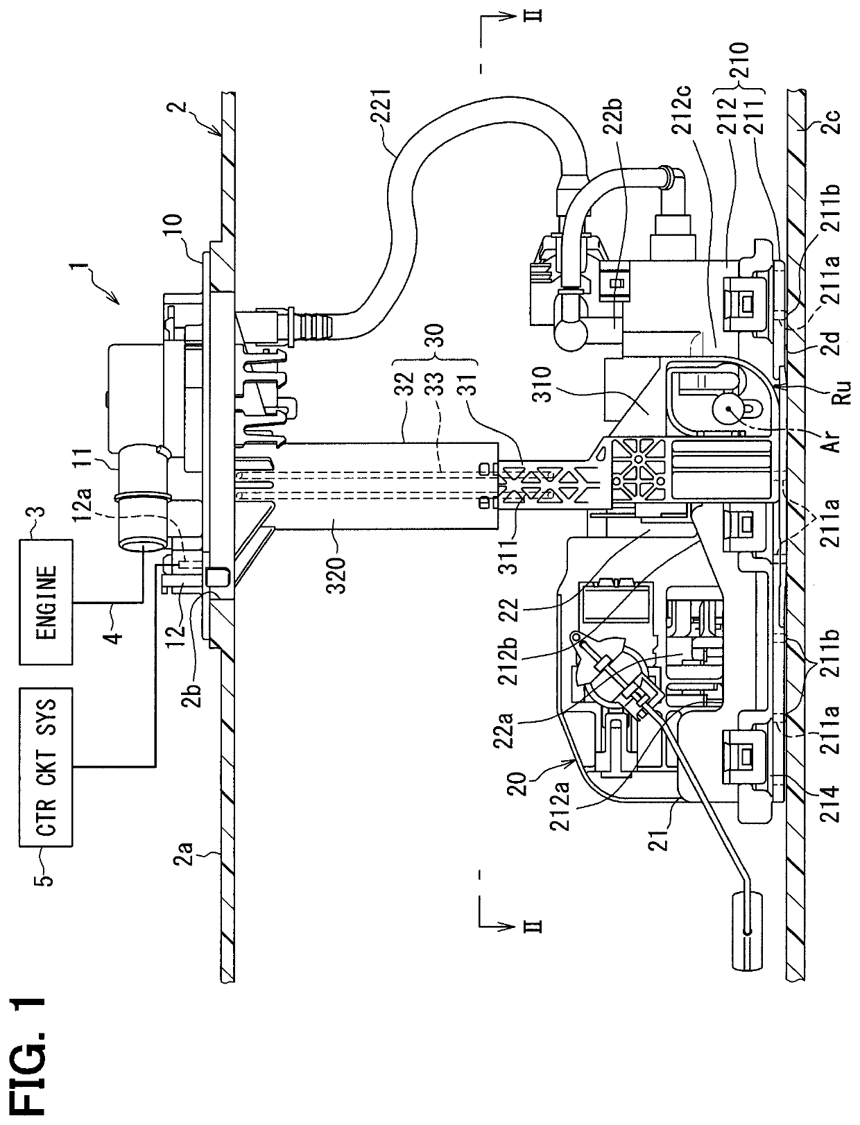
[0044]As shown in FIG. 1, a fuel supply device 1 according to a first embodiment of the present disclosure is installed to a fuel tank 2 and is thereby applied to an internal combustion engine 3 of a vehicle. The fuel supply device 1 is configured to supply fuel, which is stored in the fuel tank 2, to the internal combustion engine 3 located at an outside of the fuel tank 2. Here, the fuel tank 2 is made of resin or metal and is shaped into a hollow form. An insertion hole 2b extends through an upper wall 2a of the fuel tank 2. The fuel supply device 1 is inserted into an inside of the fuel tank 2 through the insertion hole 2b. Under the above-described inserted state, the internal combustion engine 3, which is a supply destination of the fuel from the fuel supply device 1, may be a gasoline engine or a diesel engine. A longitudinal direction and a transverse direction(s) of FIG. 1, which shows the inserted state of the fuel supply device 1 in the fuel tank 2, are respectively defin...

second embodiment

[0079]As shown in FIG. 10, a second embodiment of the present disclosure is a modification of the first embodiment.

[0080]In the second embodiment, in a rotatable plate segment 2310 of a coupling stay 2030, among two opposed peripheral edge parts 2306, 307, between which the rotational axis Ar is interposed in the one transverse direction, the radial support part Sr is decentered toward the peripheral edge part 2306 side, at which the resilient support portion 300 is formed. Therefore, according to the second embodiment, the radial support part Sr and the contact part Sc are decentered toward the peripheral edge part 2306 side and the peripheral edge part 307 side, respectively, and are thereby separated from each other, so that the line of action Lf of the restoring force F extends at the location between the radial support part Sr and the contact part Sc.

[0081]According to the second embodiment, the line of action Lf of the restoring force F, which is exerted from the resilient mem...


PUM


Abstract

A coupling stay includes a support inner peripheral surface extending along a rotational axis and providing radial support to a rotatable shaft portion of a pump unit, which extends along the rotational axis. A support lateral surface extends in a longitudinal direction and provides thrust support to the pump unit. The support inner peripheral surface extends from the support lateral surface in the transverse direction. A lock claw projects from the coupling stay. A lock projection projects from the pump unit and is operable to lock rotation of the pump unit relative to the coupling stay about the rotational axis upon fitting of the lock projection between the support lateral surface and the lock claw. A height of a contact part of the lock projection, which contacts the support lateral surface, is limited to be equal to or lower than the rotational axis.

Description

CROSS REFERENCE TO RELATED APPLICATION[0001]This application is the U.S. national phase of International Application No. PCT / JP2017 / 013162 filed on Mar. 30, 2017 which designated the U.S. and claims priority to Japanese Patent Application No. 2016-84353 filed on Apr. 20, 2016, the entire contents of each of which are hereby incorporated by reference.TECHNICAL FIELD[0002]The present disclosure relates to a fuel supply device that is configured to supply fuel from an inside of a fuel tank to an internal combustion engine.BACKGROUND ART[0003]Previously, an in-tank fuel supply device, which is placed in the inside of the fuel tank, is widely used at the internal combustion engine of a vehicle. In the device, which is disclosed in the patent literature 1 as this kind of fuel supply device, a coupling stay couples between a cover body, which is installed to an upper wall of the fuel tank, and a pump unit, which is placed on a bottom wall of the fuel tank and is operable to discharge the f...

Claims


Application Information

Patent Timeline
Patent Type & Authority Patents(United States)
IPC IPC(8): F02M37/10F02M37/00B60K15/03
CPCF02M37/00F02M37/103F02M37/10B60K15/03F02M37/0017B60K2015/03111B60K2015/03467B60K2015/03243B60K2015/03453
Inventor KOBAYASHI, KIYOMORIADACHI, RUIHAYASHI, NORIHIRO
Owner AISAN IND CO LTD
Why Eureka
Try Eureka