Rotary actuator

a technology of rotary actuators and actuators, which is applied in the direction of gearing, gearing details, hoisting equipment, etc., can solve the problems of limited concentration, cracking limited so as to restrict the breakage of the housing portion

Active Publication Date: 2016-04-05
DENSO CORP
View PDF7 Cites 7 Cited by
  • Summary
  • Abstract
  • Description
  • Claims
  • Application Information

AI Technical Summary

Benefits of technology

[0005]An objective of the present disclosure is to provide a rotary actuator capable of restricting breakage of a housing thereof.

Problems solved by technology

As a result, cracking of the housing portion due to stress concentration can be restricted, and breakage of the housing portion can be limited.

Method used


Image

  • Rotary actuator
  • Rotary actuator
  • Rotary actuator

Examples


first embodiment

(First Embodiment)

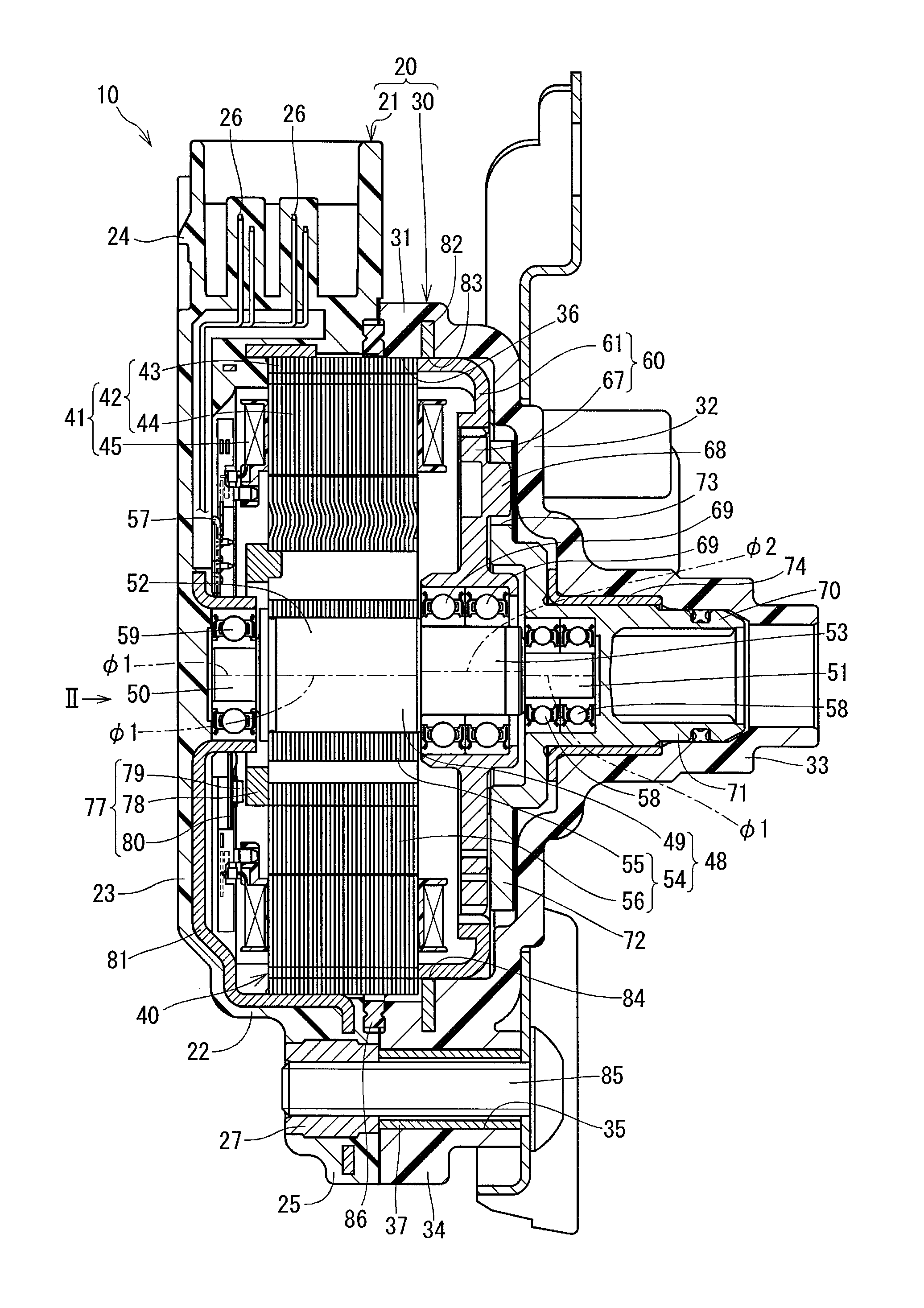
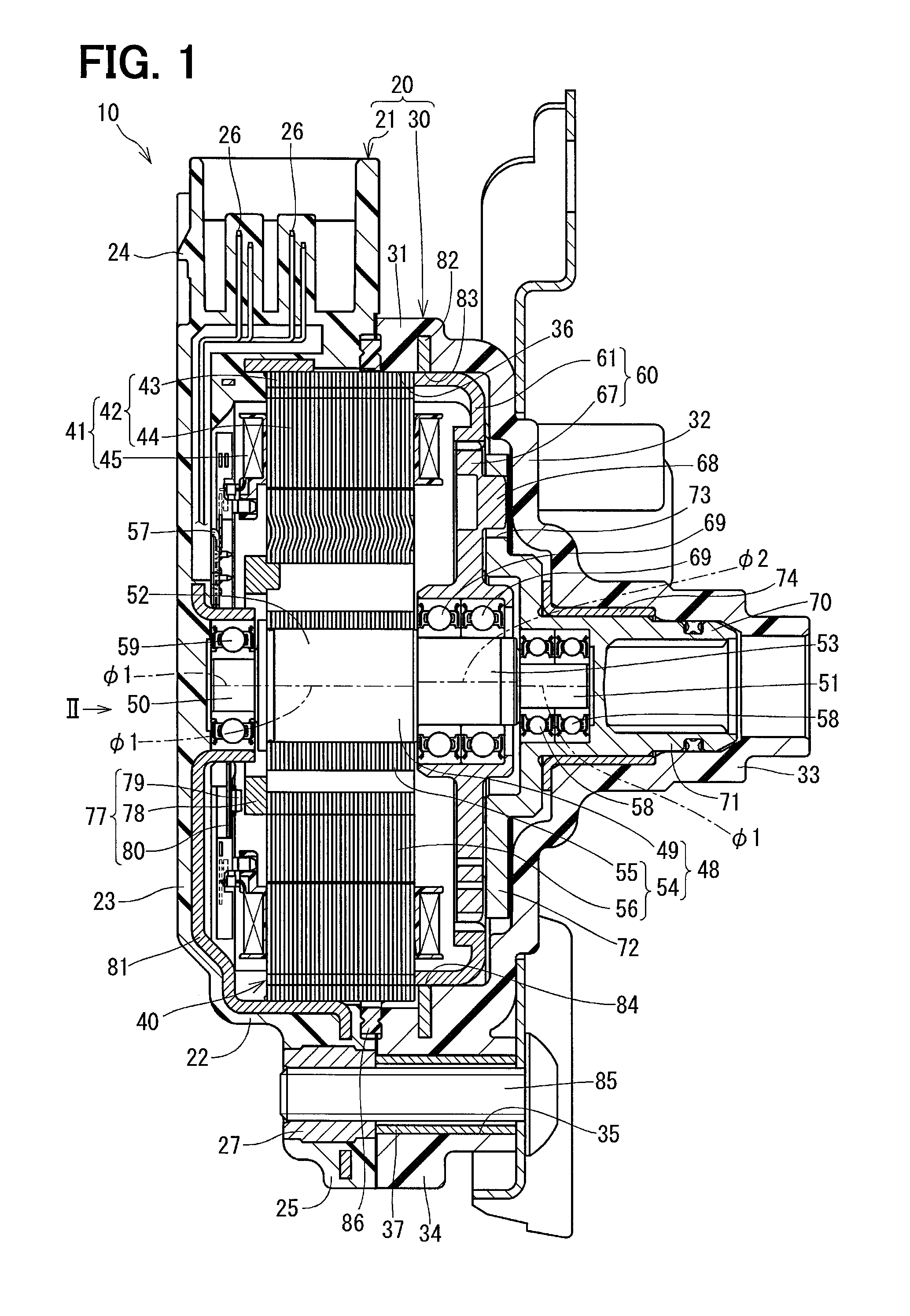
[0021]A rotary actuator 10 of a first embodiment according to the present disclosure will be described in reference to FIGS. 1 to 5. The rotary actuator 10 is used for a drive portion of a shift-by-wire system for example. The rotary actuator 10 includes a housing 20, a motor 40, a speed reduction portion 60, an output member 70 and a rotary encoder 77.

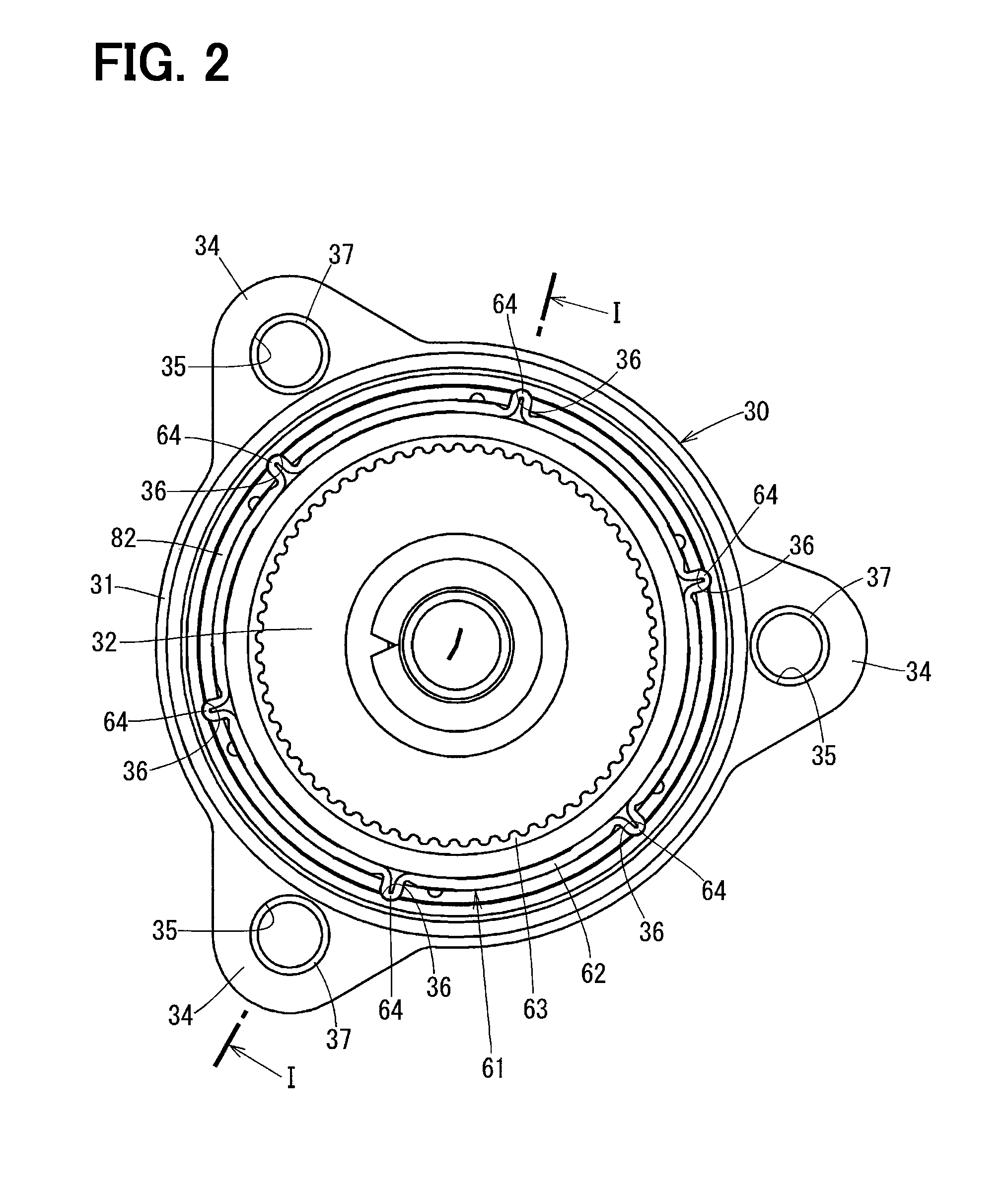
[0022]The housing 20 includes a rear housing 21 and a front housing 30. The rear housing 21 is made of resin, and the rear housing 21 includes a cylindrical portion 22, a bottom portion 23, a connector portion 24 and three attachment portions 25. The cylindrical portion 22 and the bottom portion 23 hold a metallic plate 81 having a bottomed cylindrical shape, so that the plate 81 extends into the cylindrical portion 22 and the bottom portion 23 as shown in FIG. 1. The connector portion 24 holds therein a signal pin 26 for the rotary encoder 77, and a non-shown power pin for the motor 40. The attachment portions 25 ar...

second embodiment

(Second Embodiment)

[0055]A rotary actuator 90 according to a second embodiment of the present disclosure will be described referring to FIG. 6. As shown in FIG. 6, a rotation output section the rotary actuator 90 is different from the rotation output section of the rotary actuator 10 of the first embodiment. The rotation output section of the rotary actuator 90 includes a sun gear 92, a planetary gear 93 and a planetary carrier 94.

[0056]The sun gear 92 rotates integrally with a rotor shaft 95. The planetary gear 93 engages with a ring gear 61 and the sun gear 92. When the rotor shaft 95 rotates, the planetary gear 93 revolves around a rotation axis of the rotor shaft 95 with rotating. The planetary carrier 94 is coaxial with the rotor shaft 95 to support the planetary gear 93 rotatably. The revolving motion of the planetary gear 93 is transmitted to the planetary carrier 94 so that the planetary carrier 94 rotates. The rotor shaft 95 may be used as an example of the rotation shaft.

[...


PUM


Abstract

A rotary actuator includes a rotation shaft rotatably driven by a motor, an internal gear provided on an outer side of the rotation shaft in a radial direction of the rotation shaft, a rotation output section provided between the rotation shaft and the internal gear in the radial direction to reduce a rotation speed outputted from the rotation shaft and to output a power in conjunction with the internal gear, a cylindrical housing portion fixed to the internal gear, and an attachment member integrated with an outer wall of the housing portion. The internal gear has a protrusion protruding from an outer wall of the internal gear, and the housing portion has a recess into which the protrusion is inserted. The attachment member has an attachment hole that is different from the recess in position in a circumferential direction of the housing portion.

Description

CROSS REFERENCE TO RELATED APPLICATION[0001]This application is based on and incorporates herein by reference Japanese Patent Application No. 2012-032431 filed on Feb. 17, 2012.TECHNICAL FIELD[0002]The present disclosure relates to a rotary actuator.BACKGROUND[0003]Conventionally, a rotary actuator used in, for example, a drive portion of a shift-by-wire system is known. A rotary actuator disclosed in Patent Document 1 (Japanese Patent No. 4560743 corresponding to US 2009 / 0189468) includes a speed reduction portion having an internal gear and an external gear. The internal gear is press-fitted to an inner wall of an annular plate provided in a resin housing. Protrusions provided integrally with an outer wall of the internal gear are inserted into recesses of an inner wall of the housing. The housing has an attachment holes located at positions same as positions of the recesses in a circumferential direction of the housing.[0004]In the rotary actuator disclosed in Patent Document 1, ...

Claims


Application Information

Patent Timeline
Patent Type & Authority Patents(United States)
IPC IPC(8): F16H1/32F16H57/023H02K7/116H02K5/04F16H57/02F16H55/17F16H1/28
CPCF16H1/32F16H57/023H02K5/04H02K7/116F16H1/2818F16H2055/176F16H2057/02034
Inventor KUME, MIKINENAKAYAMA, SEIJIITOH, TAKU
Owner DENSO CORP
Why Eureka
Try Eureka