Attachment structure of energy absorbing structure

a technology of energy absorption and attachment structure, which is applied in the direction of bumpers, vehicle components, vehicular safety arrangments, etc., can solve the problem of possible breakage of locking claws

Inactive Publication Date: 2009-07-07
TOYOTA JIDOSHA KK
View PDF18 Cites 6 Cited by
  • Summary
  • Abstract
  • Description
  • Claims
  • Application Information

AI Technical Summary

Benefits of technology

[0006]It is an object of the present invention to provide an attachment structure of an energy absorbing structure that can control a breakage of the locking claws disposed on the energy absorbing structure when a load in a direction along the attachment surface of the bumper reinforcement is applied to the energy absorbing structure.
[0008]In the attachment structure of an energy absorbing structure pertaining to the first aspect, when a load in a direction along the attachment surface of the bumper reinforcement is applied to the energy absorbing structure, the load receiving projections inserted into the insertion holes in the bumper reinforcement interfere with the inner peripheral portions of the insertion holes and receive the load. Consequently, transmission of the load to the locking claws can be prevented, and thus, breakage of the locking claws break can be controlled.
[0012]In the attachment structure of an energy absorbing structure pertaining to the third aspect, when a shearing load along the attachment surface of the bumper reinforcement is applied to the load receiving projections, the shearing force is transmitted to the strong solid portions because of interference between the load receiving projections and the insertion holes. Consequently, breakage of the load receiving projections can be controlled. Moreover, because the load receiving projections include the hollow portions, molding of the load receiving projections can be made easy when, for example, the energy absorbing structure is molded by injection molding.
[0014]In the attachment structure of an energy absorbing structure pertaining to the fourth aspect, the locking claws disposed on the outer peripheral portion of the energy absorbing structure engage with the outer peripheral portion of the bumper reinforcement, whereby the energy absorbing structure is locked to the bumper reinforcement. In this manner, because the locking claws are disposed on the outer peripheral portion of the energy absorbing structure where it is not prone to influence of the load applied to the energy absorbing structure, breakage of the locking claws can be controlled even more effectively.
[0016]In the attachment structure of an energy absorbing structure pertaining to the fifth aspect, the load receiving projections include convex portions disposed on the inner sides of the insertion holes, so that even when there is a clearance between the load receiving projections and the inner peripheral portions of the insertion holes, the convex portions interfere with the inner peripheral portions of the insertion holes, whereby rattling of the load receiving projections with respect to the insertion holes can be controlled.

Problems solved by technology

In this attachment structure, when a load along the vertical or lateral direction with regard to the vehicle—that is, a load in a direction along the attachment surface of the bumper reinforcement—is inputted to the energy absorbing structure, there is a possibility that the locking claws would break.

Method used


Image

  • Attachment structure of energy absorbing structure
  • Attachment structure of energy absorbing structure
  • Attachment structure of energy absorbing structure

Examples


Embodiment Construction

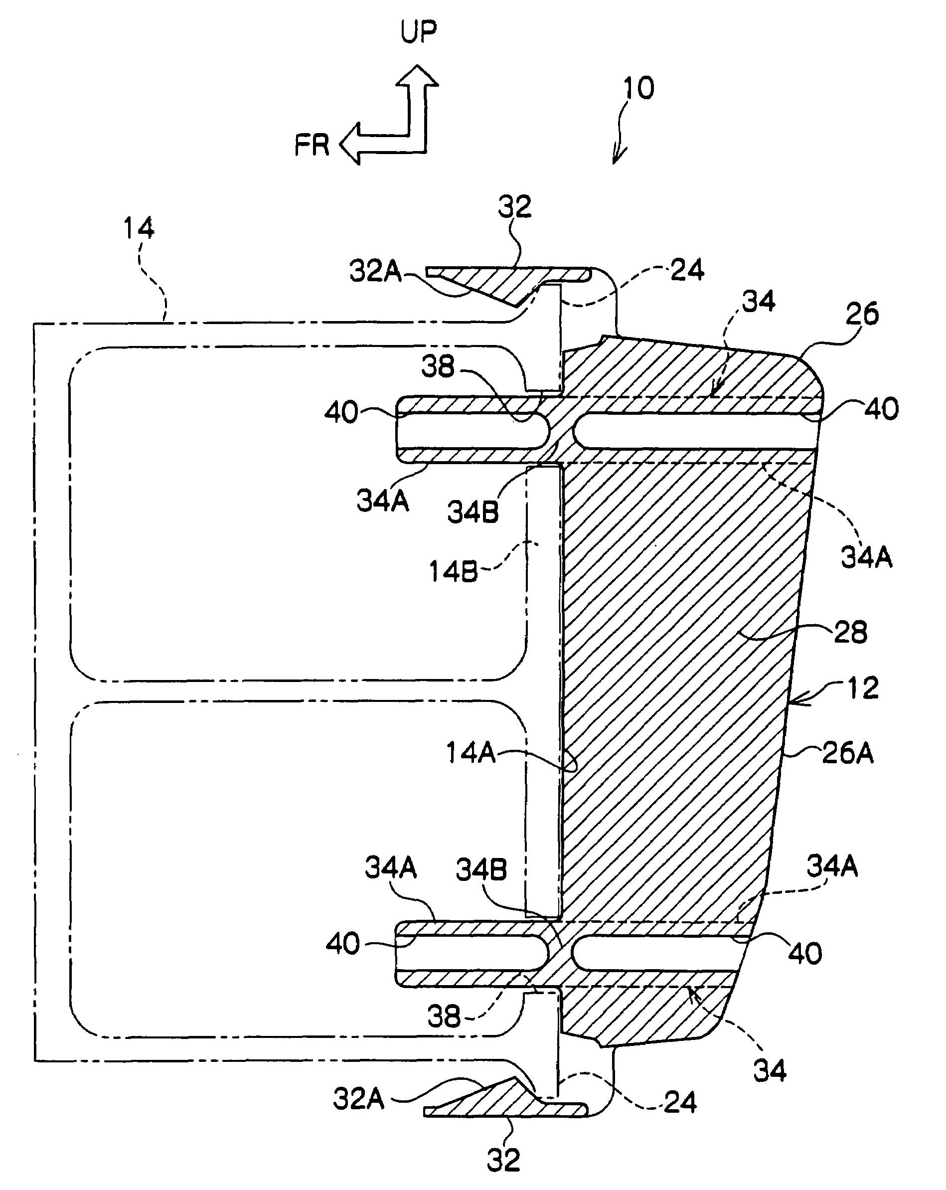
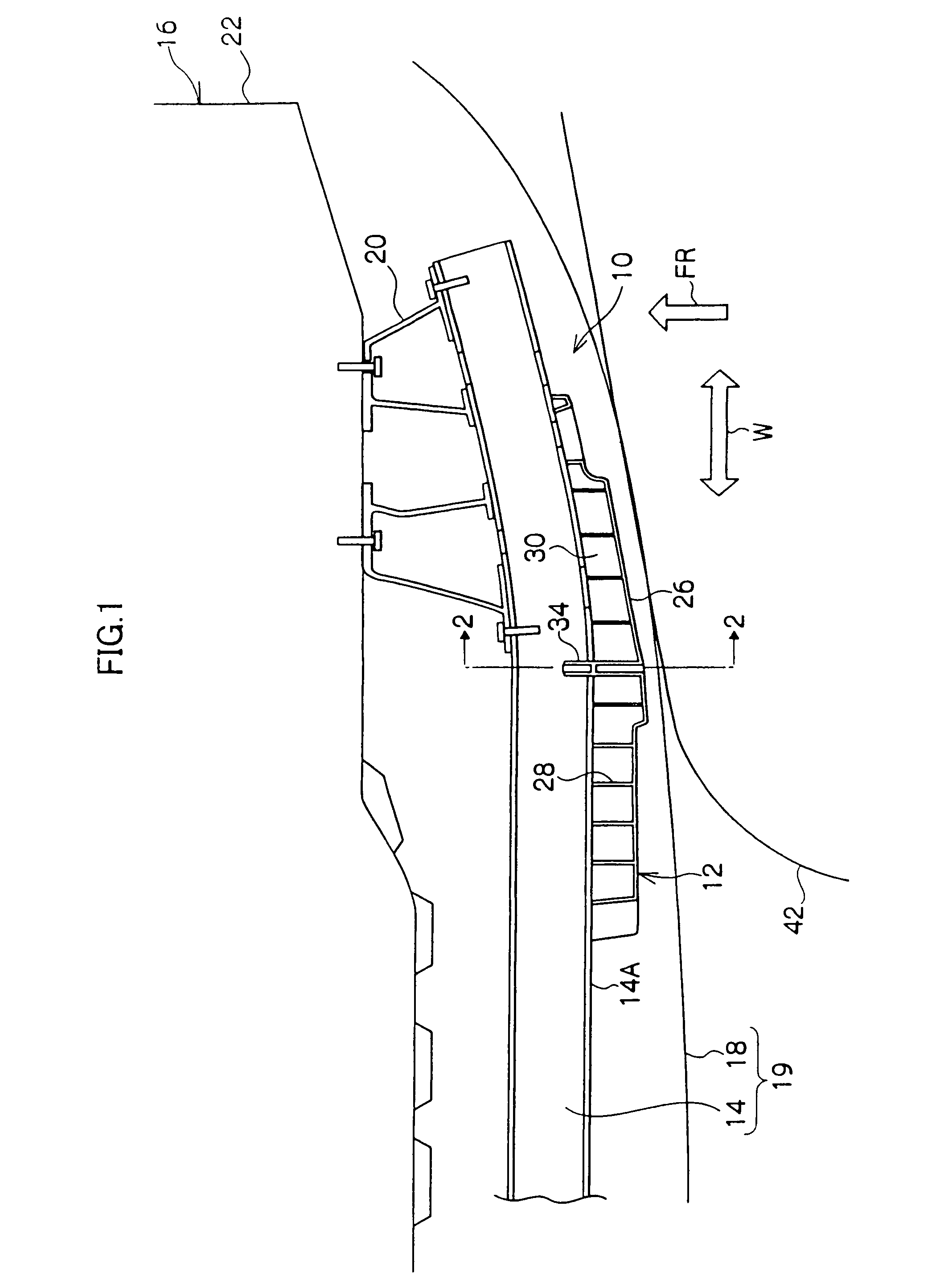
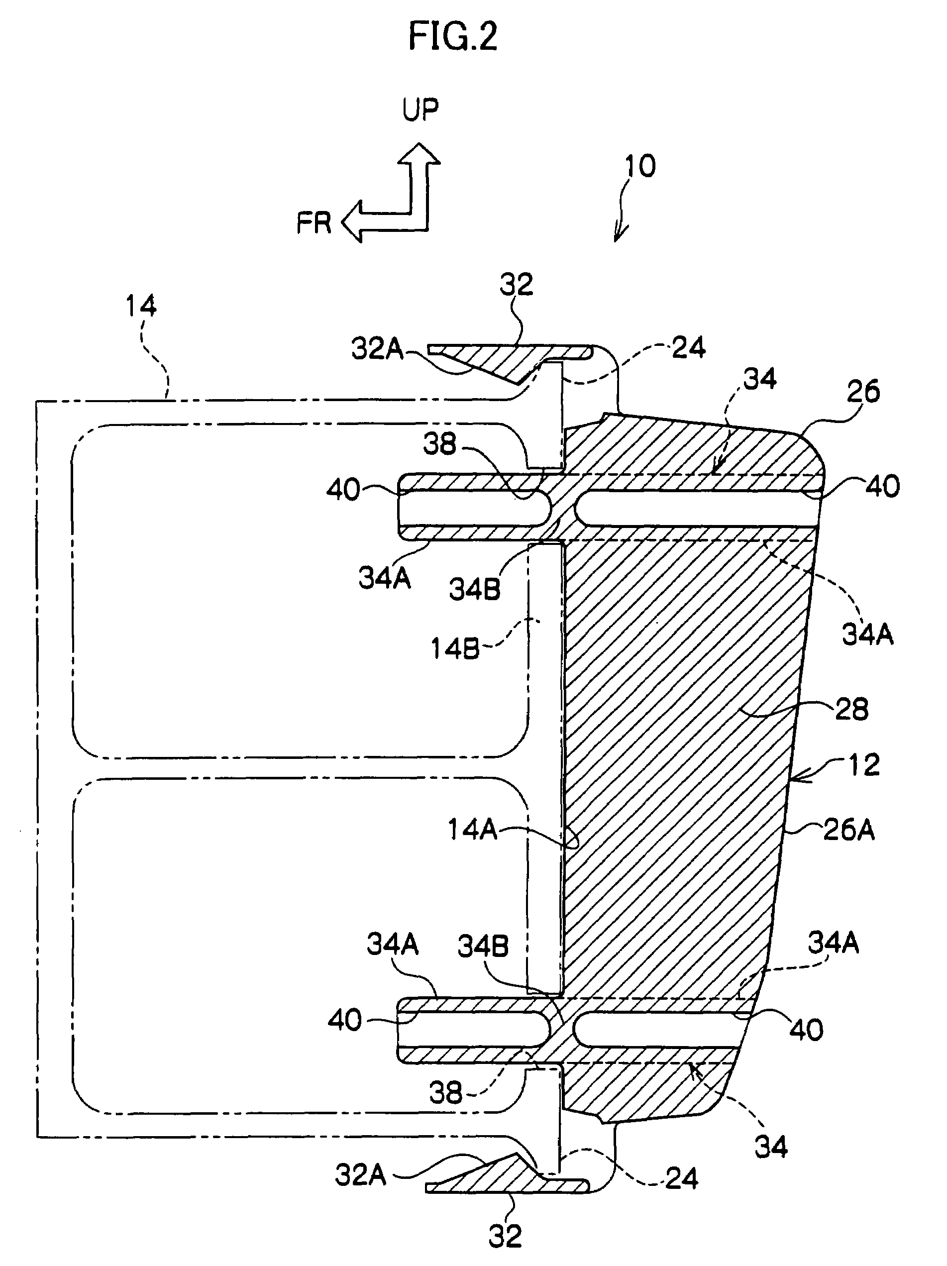
[0023]As shown in FIG. 1, an attachment structure 10 pertaining to an exemplary embodiment of the present invention is configured by a rear bumper reinforcement 14 of a vehicle 16 and by an energy absorbing structure 12 that is attached to the rear bumper reinforcement 14. It will be noted that hatching has been omitted in FIG. 1 for the convenience of description. Further, in the drawings, arrow UP, arrow FR, and arrow W represent an upward direction, a forward direction, and a width direction with regard to the vehicle 16, respectively.

[0024]As shown in FIG. 1, the rear bumper reinforcement 14 is disposed on the inner side of a rear bumper cover 18 and configures a rear bumper 19 of the vehicle 16 together with the rear bumper cover 18. The rear bumper reinforcement 14 is attached to a body 22 (vehicle body) of the vehicle 16 via rear bumper arms 20. As shown in FIG. 2, a pair of flange portions 24 that project upward and downward in the vertical direction is disposed on the vehic...


PUM


Abstract

An attachment structure of an energy absorbing structure includes: a bumper reinforcement that includes an attachment surface, with insertion holes being formed in the attachment surface; an energy absorbing structure disposed in contact with the attachment surface; locking claws that are disposed on the energy absorbing structure and engage with the bumper reinforcement to lock the energy absorbing structure to the bumper reinforcement; and load receiving projections that are disposed on the energy absorbing structure and are inserted into the insertion holes, so that when a load in a direction along the attachment surface acts on the energy absorbing structure, the load receiving projections interfere with inner peripheral portions of the insertion holes and receive the load.

Description

CROSS-REFERENCE TO RELATED APPLICATION[0001]This application claims priority under 35 USC 119 from Japanese Patent Application No. 2006-206697, the disclosure of which is incorporated by reference herein.BACKGROUND OF THE INVENTION[0002]1. Field of the Invention[0003]The present invention relates to an attachment structure for attaching an energy absorbing structure formed from a resin or the like to a bumper reinforcement of a vehicle.[0004]2. Description of the Related Art[0005]Conventionally, as an attachment structure for attaching an energy absorbing structure (shock absorbing member) to a vehicle body outer side end surface (attachment surface) of a bumper reinforcement, an attachment structure is known where, as described in JP-A No. 2004-210040, for example, flange-like projecting portions are disposed on both upper and lower end portions of a bumper reinforcement and where the energy absorbing structure is disposed with plural attachment portions—that is, locking claws—that...

Claims


Application Information

Patent Timeline
Patent Type & Authority Patents(United States)
IPC IPC(8): B60R19/18
CPCB60R19/18B60R2019/188
Inventor OHNO, YOSHIKAZUYAMAMOTO, HARUHIKOITO, TAKAO
Owner TOYOTA JIDOSHA KK
Why Eureka
Try Eureka