Power-driven shoe device

a technology of power shoe and shoe shaft, which is applied in the direction of belt/chain/gearring, toothed gearing, and belt/chain/gearring, etc., can solve the problems of reducing the volume of the transmission device, reducing the distance between the vamp and the ground, and reducing the final walking distance. , the effect of wide wheel tread

Active Publication Date: 2020-07-14
NIMBUS ROBOTICS INC
View PDF26 Cites 4 Cited by
  • Summary
  • Abstract
  • Description
  • Claims
  • Application Information

AI Technical Summary

Benefits of technology

[0006]According to the present utility model, the fixedly disposed multi-stage speed reduction structures provided by the rotating wheel racks provide an installation space, so that multi-stage speed reduction can be implemented in a relatively flat space. The multi-stage speed reduction structures effectively reduce the volume of the transmission device, and particularly reduce the size of the transmission device in a vertical direction, thereby effectively shortening the distance between the vamps and the ground to achieve higher stability of the present invention.
[0008]In order to achieve a better technical effect, a further technical measure includes that: the speed reduction gear sets are all mounted on the inner side surfaces of the rotating wheel racks, and gears in the speed reduction gear sets are located on the same straight line. When the speed reduction gear sets are located on the inner sides of the rotating wheel racks, the rotating wheel racks can achieve a good protective effect on the speed reduction gear sets. In addition, the gears in the speed reduction gear sets are located on the same straight line, so that the speed reduction gear sets occupy a reduced space in the vertical direction to further ensure that the distance between the vamps and the ground is relatively short.
[0011]According to another preferred solution, the rotating wheels at least include a first rotating wheel group and a second rotating wheel group. The driving wheel is located in the middle of a space between the first rotating wheel group and the second rotating wheel group. The speed reduction gear sets are symmetrically disposed on two sides of the driving wheel, so that the transmission device simultaneously drives the first rotating wheel group and the second rotating wheel group. In this solution, the front and rear groups of rotating wheels are driven at the same time, so that when the rear group of rotating wheels are lifted up, the front group of rotating wheels may still provide forward moving power.
[0012]A further improvement is that: the shoe sole consists of a shoe heel part and a shoe forefoot part. The shoe heel part and the shoe forefoot part are in rotatable connection with each other. The first rotating wheel group and the second rotating wheel group are both disposed on the shoe heel part. A third rotating wheel group is mounted on the lower side surface of the shoe forefoot part. The shoe heel part and the shoe forefoot part may rotate relatively, so that the present invention is more in line with the normal walking habit of a user.
[0013]The wheel tread of the first rotating wheel group and the wheel tread of the second rotating wheel group are adjustable, and the wheel tread of the first rotating wheel group is less than or equal to that of the second rotating wheel group. With the adjustable wheel treads, the present utility model is applicable to people of different sports demands. With wide wheel treads, it is applicable to people requiring stability. With narrow wheel treads, it is applicable to people requiring movability. In addition, the wheel tread of the first rotating wheel group is less than or equal to that of the second rotating wheel group, so that the transverse steadiness is improved, and such a phenomenon that the forefoot part of one shoe collides with the heel of the other shoe during walking due to an extremely wide wheel tread is avoided.
[0014]Compared with the prior art, the present utility model has the following beneficial effects that: the fixedly disposed multi-stage speed reduction structures provided by the rotating wheel racks provide an installation space, so that multi-stage speed reduction can be implemented in the relatively flat space. The multi-stage speed reduction structures effectively reduce the volume of the transmission device, and particularly reduce the size of the transmission device in the vertical direction, thereby effectively shortening the distance between the vamps and the ground to achieve higher stability of the present invention.

Problems solved by technology

Although public transportation is a very effective solution to the traffic jam, a last kilometer problem, that is, a relatively long final walking distance, still remains, which is one of the factors hindering the building of a perfect bus system.
However, the existing electric roller skates have one problem that: an enough space must be reserved between shoe soles and the ground because transmission structures are not small enough, resulting in a relatively long distance between vamps and the ground; and furthermore, the wheel tread is relatively small, so that the stability is extremely low, and only those who are skilled at roller skating can use the electric roller skates successfully.
If the wheel tread is increased, two feet would collide with each other to cause falling over during walking due to extremely wide vamps, so that the electric roller skates are very unsafe to use on the road.

Method used


Image

  • Power-driven shoe device

Examples


embodiment 1

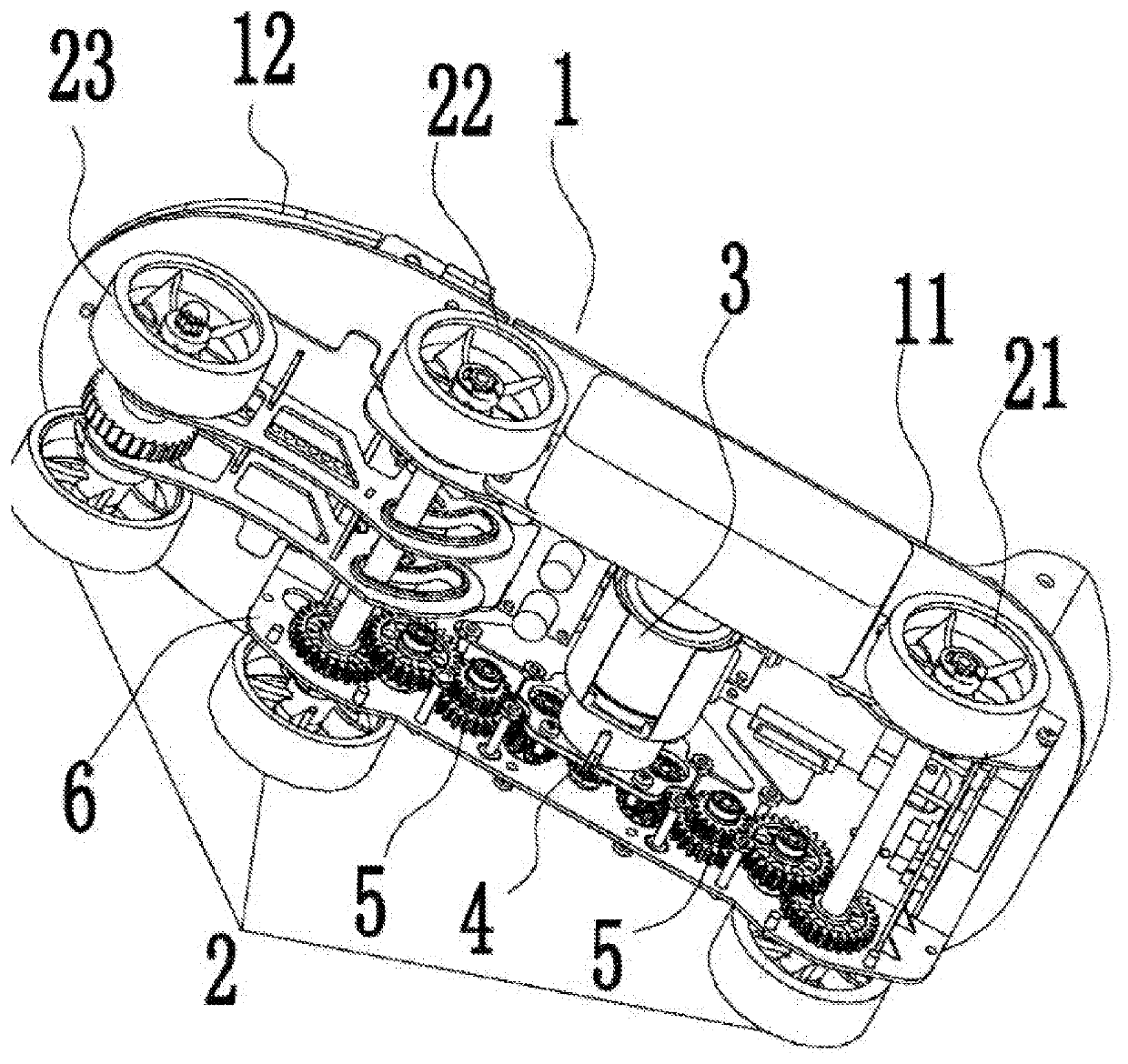
[0017]With reference to FIG. 1, power shoe devices are provided, each of which includes a shoe sole 1. A plurality of rotating wheels 2 are disposed below the shoe sole 1, and a motor 3 is further disposed at the lower part of the shoe sole 1; and the output end of the motor 3 is connected with a transmission device which is in driving connection with the rotating wheels 2. Each power shoe device is characterized in that rotating wheel racks 6 for mounting the rotating wheels 2 are disposed on two sides of the lower side surface of the shoe sole 1. The transmission device includes a driving wheel 4 and multi-stage speed reduction structures which are disposed on the rotating wheel racks 6 along the lengthwise direction of the shoe sole 1. The transmission device further includes a planetary speed reducer which is connected with the motor 3.

[0018]The rotating wheel racks 6 for mounting the rotating wheels 2 are disposed on the two sides of the lower side surface of the shoe sole 1. S...

embodiment 2

[0021]In this embodiment (the FIGURE is omitted), the rotating wheels 2 at least include a first rotating wheel group 21 and the second rotating wheel group 22. The wheel tread of the first rotating wheel group 21 is less than that of the second rotating wheel group 22. The transmission device drives the second rotating wheel group 22.

[0022]The rest part is the same as that of Embodiment 1, so no more details will be given herein.

[0023]In addition to the speed reduction gear sets, the multi-stage speed reduction structures in the above-mentioned embodiment may also adopt synchronous belt wheels and other speed reduction structures.


PUM


Abstract

Disclosed is a power-driven shoe device, comprising a shoe sole (1), wherein a plurality of rotating wheels (2) are arranged below the shoe sole (1); an electric motor (3) is further provided at a lower part of the shoe sole (1); an output end of the electric motor (3) is connected to a transmission device; the transmission device is in driving connection with the rotating wheels (2); rotating wheel brackets (6) for having the rotating wheels (2) mounted thereon are arranged on two sides of a lower side surface of the shoe sole (1); and the transmission device comprises a driving wheel (4), a multistage deceleration structure and a planetary speed reducer, the multistage deceleration structure being disposed, in a lengthwise direction of the shoe sole (1), on the rotating wheel brackets (6).

Description

TECHNICAL FIELD[0001]The present invention relates to the technical field of transportation tools, and more particularly relates to power shoe devices.BACKGROUND ART[0002]With the further growth of the urban population, traffic jam has become the nuisance of every main city. Although public transportation is a very effective solution to the traffic jam, a last kilometer problem, that is, a relatively long final walking distance, still remains, which is one of the factors hindering the building of a perfect bus system. Traditional roller skates can solve the above-mentioned problem to a certain extent, and there are various electric transportation tools on the market, such as electric roller skates appearing recently, which are the solutions to the last kilometer problem.[0003]However, the existing electric roller skates have one problem that: an enough space must be reserved between shoe soles and the ground because transmission structures are not small enough, resulting in a relati...

Claims


Application Information

Patent Timeline
Patent Type & Authority Patents(United States)
IPC IPC(8): A63C17/12A63C17/04A63C17/22F16H3/66
CPCA63C17/12A63C17/226A63C17/04F16H3/66A63C17/262A63C2203/12F16H1/22
Inventor ZHANG, JIANCHENGXU, BOJIELI, JIANJUNSONG, DONGLIANG
Owner NIMBUS ROBOTICS INC
Why Eureka
Try Eureka