Pool pumping apparatus

Active Publication Date: 2020-07-14
RICKERSON RUSSEL
View PDF21 Cites 2 Cited by
  • Summary
  • Abstract
  • Description
  • Claims
  • Application Information

AI Technical Summary

Benefits of technology

[0008]Still another object of this invention is to provide a pool pumping apparatus, as aforesaid, having a vacuum breake

Problems solved by technology

Leaving a pool completely drained may lead to damage to vinyl or concrete surfaces.
However, it is equally importan

Method used


Image

  • Pool pumping apparatus
  • Pool pumping apparatus
  • Pool pumping apparatus

Examples


Example

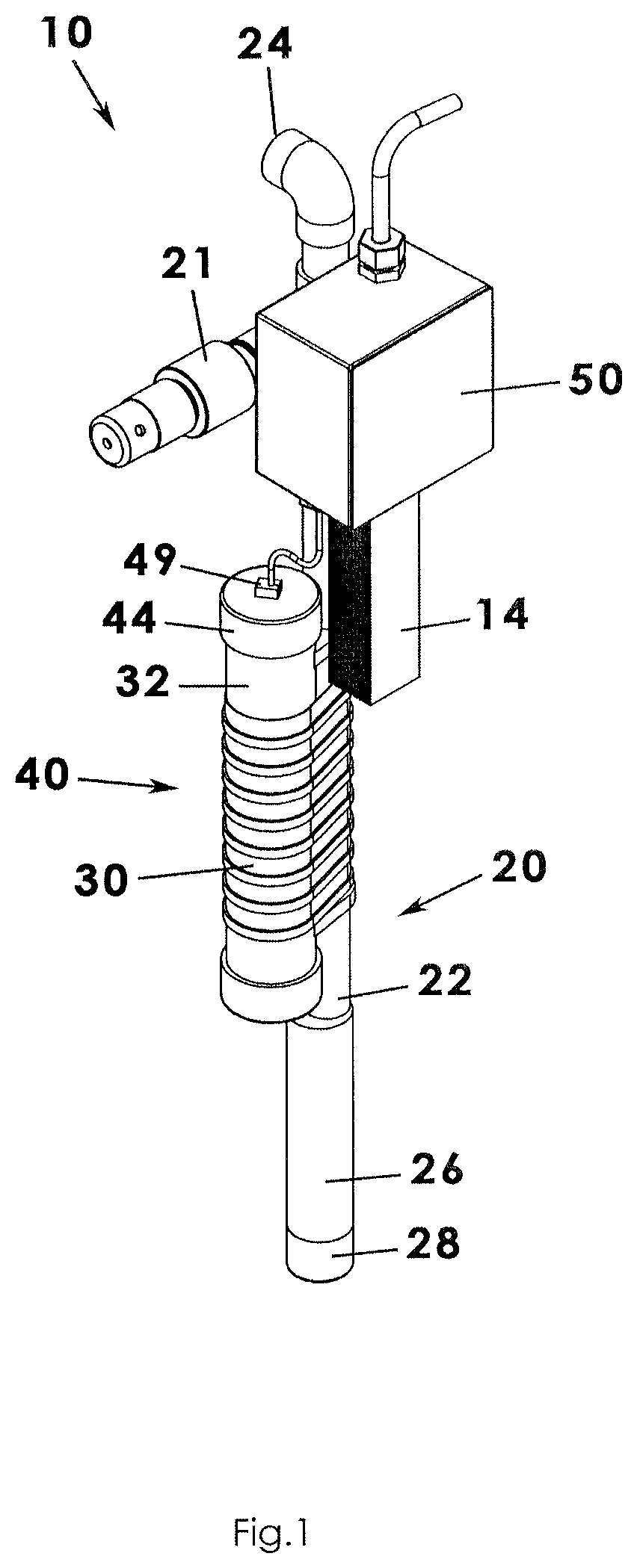
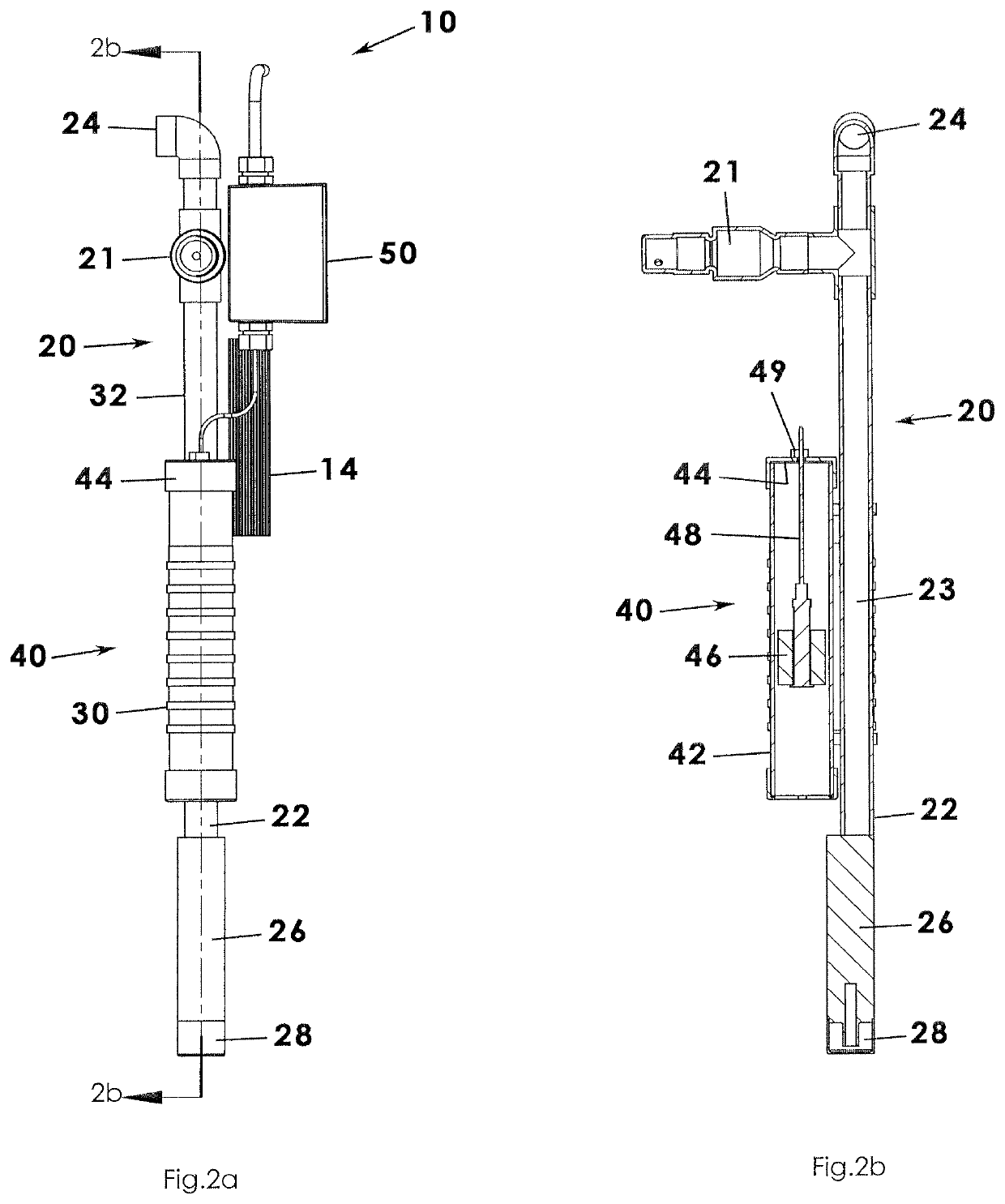
[0019]A pool pumping apparatus according to a preferred embodiment of the present invention will now be described with reference to FIG. 1 to 4c of the accompanying drawings. The pool pumping apparatus 10 includes a conduit 20, a pump 26, and a float assembly 40 that, together, maintain a constant and predetermined level of water in a swimming pool 12.

[0020]The pool pumping apparatus 10 includes a conduit 20 having a generally linear configuration defining a longitudinal axis. It is understood that the conduit 20 may sometimes be referred to as a channel as water from the swimming pool 12 will be channeled through the conduit 20 as explained below. The conduit 20 may be a pipe constructed of metal or plastic and, preferably, has a cylindrical configuration defining an interior area. The conduit 20 has an inlet 22 at an open proximal end and has an outlet 24 at an open distal end, the proximal and distal ends being opposite one another. Water (or referred to as a water stream) enters...


PUM


Abstract

A pool pumping apparatus for maintaining a constant level of water in a swimming pool includes a conduit having a lower end defining an inlet and an outlet that are open, the conduit defining an interior area through which water is channeled between the inlet and outlet. The apparatus includes a pump in fluid communication with the inlet of the conduit, the pump having a motor configured to transfer water from the inlet to the outlet when energized. In addition, a float assembly includes a housing that defines an interior space and includes a float member positioned in the interior space, the float assembly including a cord extending from the float member operable for setting the float member at a selected level. The float member is electrically connected to the pump and configured to energize the pump when the float member is above the selected level.

Description

BACKGROUND OF THE INVENTION[0001]This invention relates generally to pumping devices and, more particularly, to a pool pumping apparatus for maintaining a consistent level or depth of water in a swimming pool by pumping water out of the pool onto the ground or into a drain whenever a predetermined overage is detected.[0002]It is important to leave a certain level of water in a residential swimming pool over the course of a winter. Leaving a pool completely drained may lead to damage to vinyl or concrete surfaces. In other words, leaving an amount of water in the pool can help protect its surfaces—not to mention keeping an above ground pool heavy enough to be grounded against winter winds. However, it is equally important not to allow water to enter the skimmer or other pool hardware that could be ruined if that water was to freeze. In short, the level of water in a pool should be monitored over the course of the winter and the level reduced if it has naturally increased to a level t...

Claims


Application Information

Patent Timeline
IPC IPC(8): E04H4/12F04D13/08G01F23/60
CPCG01F23/60E04H4/12F04D13/086E04H4/1245G01F23/0007G01F23/303G01F23/74G01F23/76
Inventor RICKERSON, RUSSEL
Owner RICKERSON RUSSEL
Why Eureka
Try Eureka