
Image forming apparatus

a technology of forming apparatus and forming chamber, which is applied in the direction of electrographic process apparatus, corona discharge, instruments, etc., can solve the problems of non-uniform density image or the like, non-uniform amount by which contaminated toner is ejected to be created, and the adherent to the contact charging member may sometimes occur, etc., to reduce the wait time of users, suppress the ejection of contaminated toner, suppress the effect of deteriora

Active Publication Date: 2020-07-14
CANON KK
View PDF10 Cites 0 Cited by
  • Summary
  • Abstract
  • Description
  • Claims
  • Application Information

AI Technical Summary

Benefits of technology

The patent describes a technique for reducing the waiting time for users and preventing uneven image quality in an image forming apparatus with multiple image forming portions. The technique involves suppressing the ejection of contaminated toner from the non-image forming portion and deterioration of the image bearing member. This results in improved user experience and reduced occurrence of quality issues.

Problems solved by technology

However, in image forming apparatuses adopting an image bearing member cleaner-less system as described above, there are several problems when executing an image formation mode in which a non-image forming portion is present among image forming portions arranged in plurality.
As a first problem, in the non-image forming portion, when a charging bias to be applied to a contact charging member is turned off or set lower than during image formation, a non-uniform density image or the like caused by ejection of toner (hereinafter, contaminated toner) adhered to the contact charging member may sometimes occur.
In addition, when the contaminated toner is ejected, a surface potential non-uniformity or the like of the image bearing member may cause a non-uniformity in an amount by which the contaminated toner is ejected to be created.
Subsequently, when image formation is next performed by the same image forming portion, the toner contamination non-uniformity of the contact charging member prevents the image bearing member from being uniformly charged and results in an occurrence of image defects such as a non-uniform density image in a printed portion and background fogging in a non-printed portion.
There is also a problem when, in order to suppress occurrences of such image defects, a transfer bias is controlled such that the contaminated toner is recovered by another image forming portion on a downstream side of a movement direction of an intermediate transfer member so as to prevent the contaminated toner from being recovered once again by the contact charging member upon ejection.
As described above, the ejection of contaminated toner from the contact charging member of a non-image forming portion may cause various image defects.
However, as a second problem, discharge from the contact charging member promotes deterioration of the image bearing member of the non-image forming portion in the form of abrasion and adhesion of discharge products even though the image bearing member is not used for image formation.

Method used


Image

  • Image forming apparatus
  • Image forming apparatus
  • Image forming apparatus

Examples


embodiments

Overall Configuration of Image Forming Apparatus

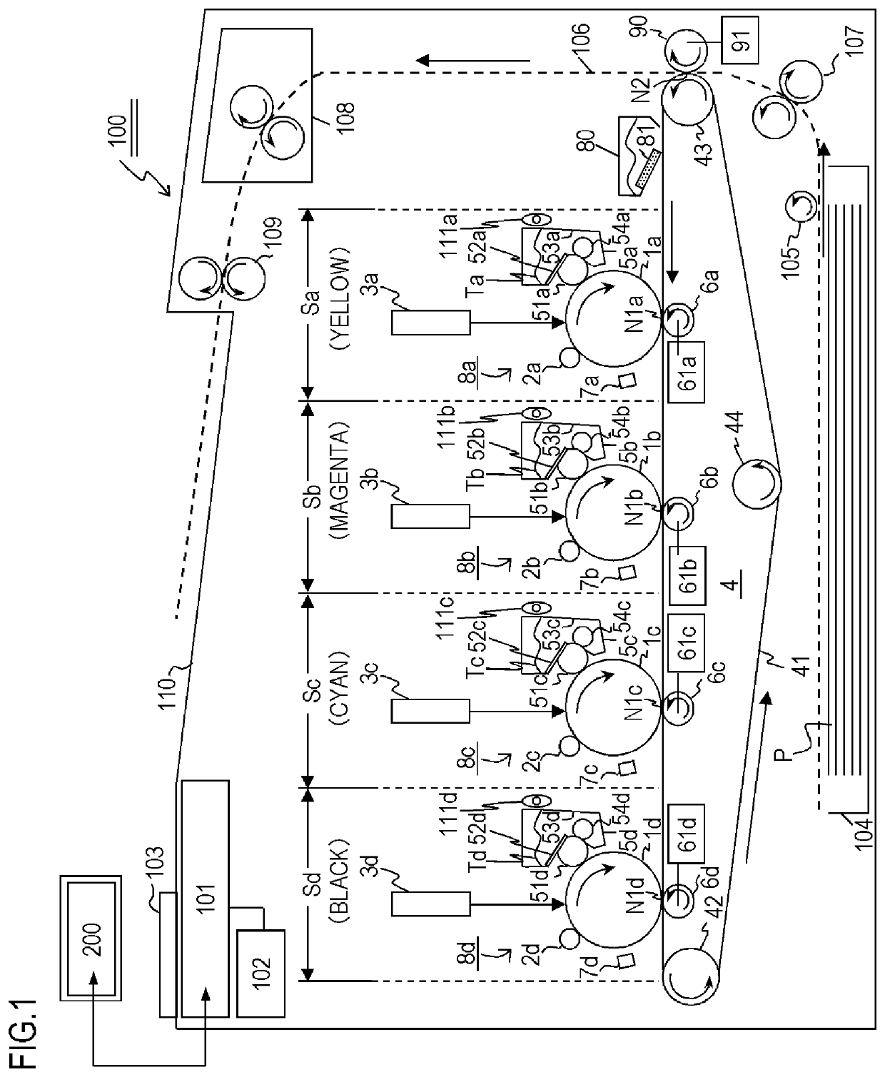
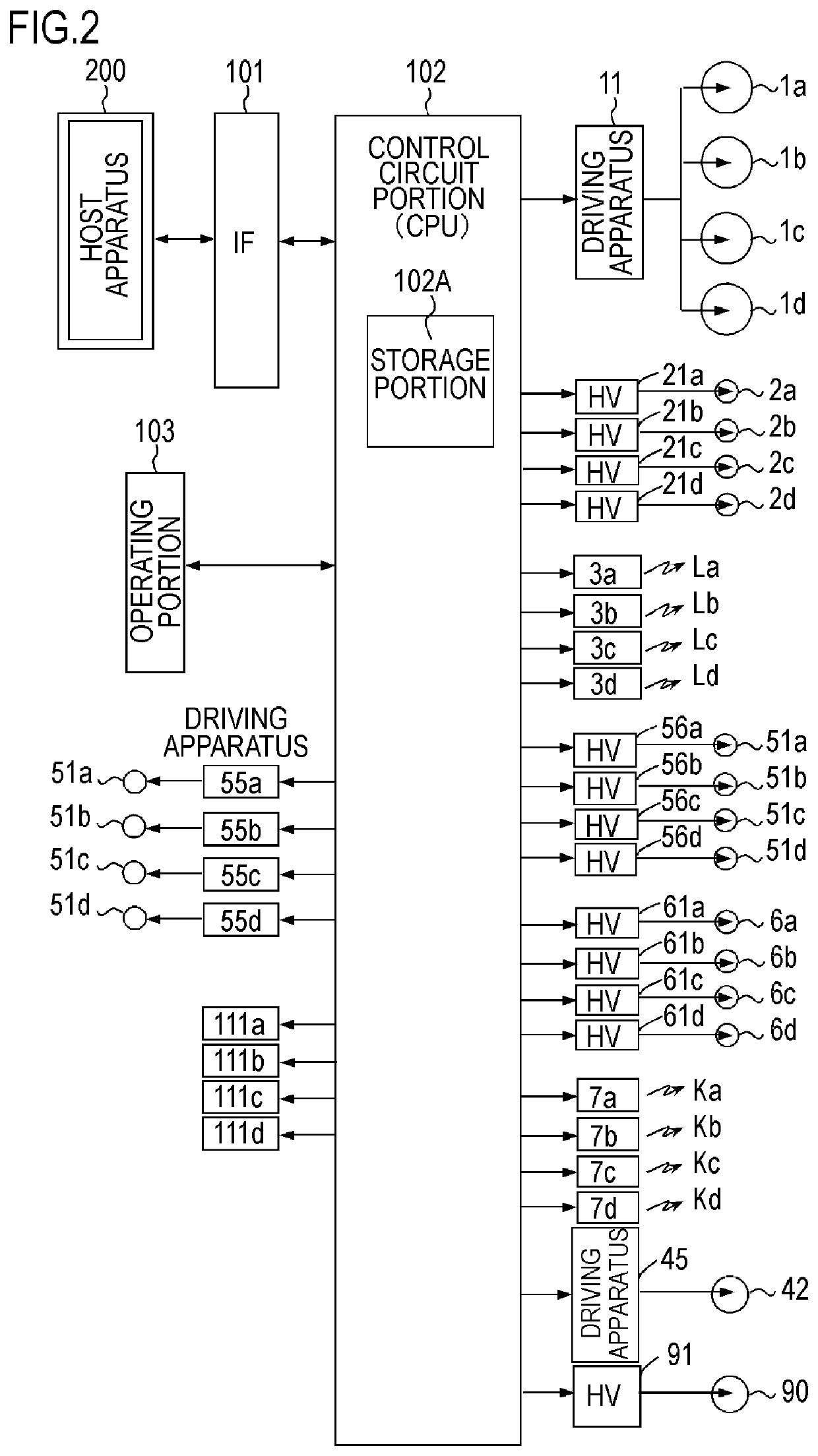
[0041]FIG. 1 is a configuration schematic view of key portions of an image forming apparatus 100 according to the present embodiment. FIG. 2 is a block diagram of a control system of the key portions of the image forming apparatus 100. The apparatus 100 is an electrophotographic color laser beam printer adopting an intermediate transfer system and an in-line system as an example of an image forming apparatus to which the present disclosure can be applied. The apparatus 100 receives an input of an image signal (electric image information) that is input from a host apparatus 200 to a control circuit portion (a CPU: control means) 102 via image signal receiving means (IF) 101. Based on the input image signal, the control circuit portion 102 executes a full-color mode (a multicolor image formation mode) in which image formation in multiple colors is performed on a recording material (a transfer material) P or a monochrome mode (a monochrom...

second embodiment

[0123]An image forming apparatus according to a second embodiment of the present disclosure will be described with reference to FIG. 9. Since an apparatus configuration of the image forming apparatus according to the second embodiment does not differ from the apparatus configuration of the image forming apparatus according to the first embodiment, a description thereof will be omitted below. A potential relationship between the charging roller 2 and the drum 1 which contributes to movement of toner will be described with reference to FIG. 9 while comparing control operations in chronological order with those of the first embodiment. FIG. 9 is a timing chart during image formation including the monochrome mode B in the color image forming portions Sb and Sc according to the second embodiment. In addition, a potential relationship between the charge upstream drum potential Vd1 and the charging bias Vc at respective timings is shown in FIG. 9. The suffixes b (magenta) and c (cyan) will...

third embodiment

[0128]An image forming apparatus according to a third embodiment of the present disclosure will be described with reference to FIG. 10. Since an apparatus configuration of the image forming apparatus according to the third embodiment does not differ from the apparatus configuration of the image forming apparatus according to the first embodiment, a description thereof will be omitted below. A potential relationship between the charging roller 2 and the drum 1 which contributes to movement of toner will be described with reference to FIG. 10 while comparing control operations in chronological order with those of the first embodiment. FIG. 10 is a timing chart during image formation including the monochrome mode B in the color image forming portions Sb and Sc according to the third embodiment. In addition, a potential relationship between the charge upstream drum potential Vd1 and the charging bias Vc at respective timings is shown in FIG. 10. The suffixes b (magenta) and c (cyan) wil...


PUM


Abstract

In an image forming operation of transferring one developer image to a recording material, when a plurality of image forming portions include a non-image forming portion that is an image forming portion which does not form a developer image on an image bearing member, applying means for applying a charging bias to a charging member which comes into contact with and charges the image bearing member applies a second charging bias to the charging member in the non-image forming portion, the second charging bias having a same polarity as a first charging bias for forming a developer image and being a voltage equal to or lower than a discharge start voltage.

Description

BACKGROUND OF THE INVENTIONField of the Invention[0001]The present disclosure relates to an image forming apparatus which forms an image on a recording material using an electrophotographic technique.Description of the Related Art[0002]Among image forming apparatuses such as copiers and printers which use an electrophotographic system, 4-color full color image forming apparatuses adopting an intermediate transfer system have a mode such as a monochrome mode in which image formation is performed using only a part (one) of a plurality of image forming portions. In doing so, in image forming portions not performing image formation (hereinafter, non-image forming portions), a charging bias to be applied to charging means is generally turned off or set lower than during image formation. In addition, by selecting and executing such an image formation mode in accordance with image information and the like, deterioration of an image bearing member (a photosensitive drum) in non-image formin...

Claims


Application Information

Patent Timeline
Patent Type & Authority Patents(United States)
IPC IPC(8): G03G15/00G03G15/22G03G15/16G03G15/01G03G15/02
CPCG03G15/0142G03G15/0258G03G15/0189G03G15/5004G03G15/0266G03G15/161G03G2215/00025
Inventor MUKAI, TAKASHIOKUBO, KAZUHIROKAWAMOTO, TAKAHIROTANAKA, MASANORI
Owner CANON KK
Learn More