System and method for modeling signal flows in automation technology equipment

a technology of automation technology and signal flow, applied in the field of system and method for generating a behavior model for the simulation of an automation system, can solve the problems of high complexity of control software for controlling the components of this known equipment, high complexity of known production-engineering equipment, and easy errors, so as to achieve the maximum possible data consistency, increase user convenience, and facilitate simulation

Active Publication Date: 2020-07-21
SIEMENS PROD LIFECYCLE MANAGEMENT SOFTWARE INC
View PDF9 Cites 0 Cited by
  • Summary
  • Abstract
  • Description
  • Claims
  • Application Information

AI Technical Summary

Benefits of technology

[0017]Consequently, the user of the system in accordance with the invention is able to model a signal flow between two components without having to draw connection lines for this purpose. This also avoids the problem of overlapping connection lines which lead to unclear signal flow diagrams. Compared with this, the modeling of signal flows in accordance with the invention is highly intuitive and offers a very clear representation even in large automation technology plants.
[0029]In a further advantageous embodiment of the invention, the second, third and fourth means and, if present, the fifth, sixth, seventh and eighth means, are integrated in an engineering system. Such an engineering system makes it possible to use the CAD data produced in an early planning phase also during simulation of the planned automation system and consequently enables maximum possible data consistency in the planning phase.

Problems solved by technology

Known production-engineering equipment, however, is very complex and highly automated.
The control software needed for controlling the components of this known equipment is likewise of considerable complexity.
Depending on the complexity and multiplicity of the components used in the automation system, the simulation of these signal flows is extremely complicated for the user and prone to errors.
The more complex the structure of the automation system to be modeled, the more prone such an approach is to errors.
In addition, the definition of signal flows in the form of graphic connecting lines frequently results in a highly unclear representation which makes locating errors extremely difficult.

Method used


Image

  • System and method for modeling signal flows in automation technology equipment
  • System and method for modeling signal flows in automation technology equipment
  • System and method for modeling signal flows in automation technology equipment

Examples


Embodiment Construction

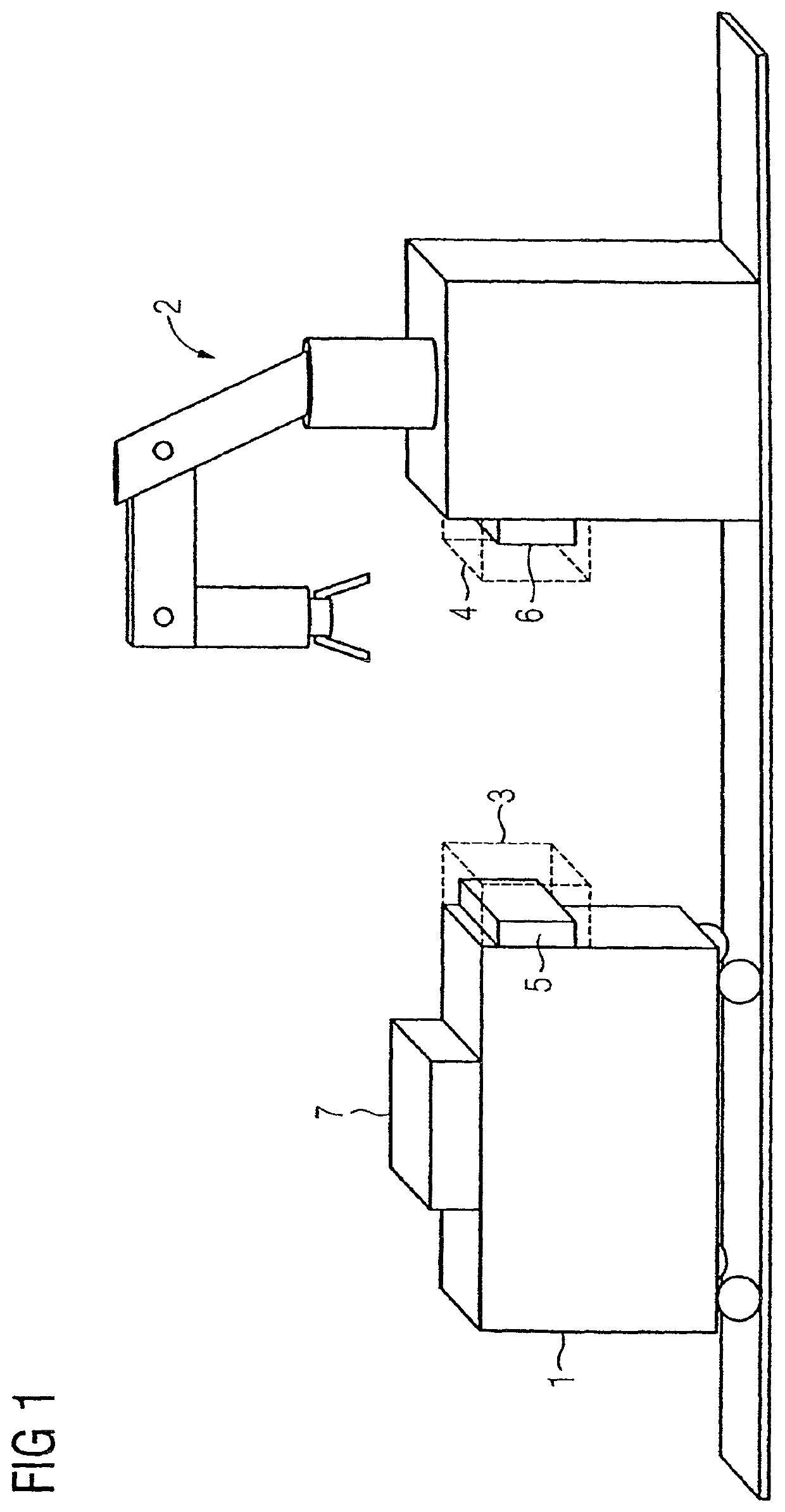
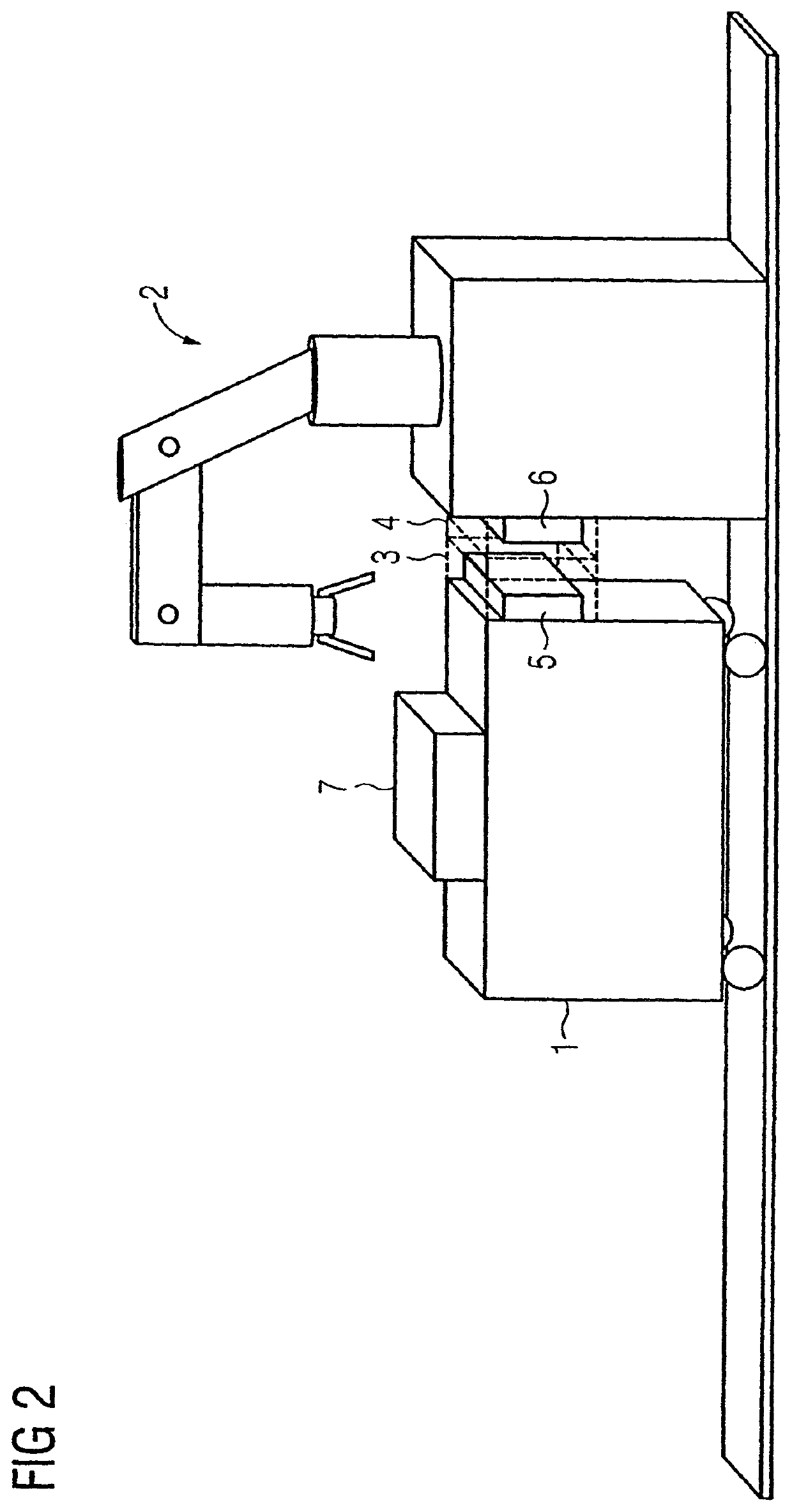
[0036]FIG. 1 shows a CAD drawing as a basis for generating a behavior model comprising a system in accordance with an embodiment of the invention, components 1,2 with open data interfaces 5,6 being represented. The drawing was developed with the aid of a CAD environment which is part of an extensive engineering system for the planning and designing automation systems. In the automation systems to be planned, workpieces 7 are moved on autonomous transport units, the figure showing by way of example the CAD representation of one of these transport units. Thus, a first component 1 of the automation system represents such a traveling transport unit which comprises a receptacle for a workpiece 7. A second component 2 of the automation system forms a processing station which is intended for processing the transported workpiece 7. The first component 1 transports the workpiece 7 during a production process to be simulated to the second component 2. The first component 1 contains a first in...


PUM


Abstract

A system and method for generating a behavior model for simulating an automation system, wherein signal flows between components of the automation system are simulated. The system comprises a CAD application for developing CAD drawings of the components of the automation system, where the CAD application comprises first modules for defining a geometric scope of application for the data interfaces of the components, second modules for defining at least one signal transmission prerequisite, which marks at least one relative position of two scopes of application relative to each other, at which signal transmission is possible between associated data interfaces, third modules for verifying the compatibility of the data interfaces at which the signal transmission prerequisite is met, and fourth modules for generating the behavior model such that a signal flow between the data interfaces at which the signal transmission prerequisite and compatibility are met is modeled in the simulation.

Description

CROSS-REFERENCE TO RELATED APPLICATIONS[0001]This is a U.S. national stage of International Application No. PCT / EP2007 / 008329, filed on 25 Sep. 2007.BACKGROUND OF THE INVENTION[0002]The invention relates to a system and method for generating a behavior model for the simulation of an automation system, in which signal flows between components of the automation system are simulated.[0003]It is known to use a system or method for planning and designing systems for production and / or process automation. Known production-engineering equipment, however, is very complex and highly automated. The control software needed for controlling the components of this known equipment is likewise of considerable complexity. For an automation technology system to be put into operation smoothly, it is therefore desirable for the control software to be tested before placing the an automation system into operation. Simulations of the automation equipment are therefore nowadays increasingly performed in adv...

Claims


Application Information

Patent Timeline
Patent Type & Authority Patents(United States)
IPC IPC(8): G05B19/418G05B19/042
CPCG05B19/41885G05B19/0426Y02P90/265G05B2219/32351G05B2219/23005G05B2219/23448G05B2219/23456Y02P90/26G05B2219/32345Y02P90/02
Inventor STOLPER, THILO
Owner SIEMENS PROD LIFECYCLE MANAGEMENT SOFTWARE INC
Why Eureka
Try Eureka