Check patentability & draft patents in minutes with Patsnap Eureka AI!

Cooling passage with structural rib and film cooling slot

a cooling passage and film cooling technology, applied in the direction of machines/engines, stators, mechanical equipment, etc., can solve the problems of increasing inconfigurability to provide sufficient cooling for constituent materials

Active Publication Date: 2020-07-28
RTX CORP
View PDF13 Cites 1 Cited by
  • Summary
  • Abstract
  • Description
  • Claims
  • Application Information

AI Technical Summary

Benefits of technology

This design improves thermal conditioning of turbine components by ensuring even airflow distribution and increased heat transfer, thereby extending the service life and maintaining components within a desired temperature range.

Problems solved by technology

In the ongoing efforts to improve engine performance and efficiency, these configurations are becoming increasingly inadequate to provide sufficient cooling for the constituent materials.

Method used


Image

  • Cooling passage with structural rib and film cooling slot
  • Cooling passage with structural rib and film cooling slot
  • Cooling passage with structural rib and film cooling slot

Examples


Embodiment Construction

[0034]A detailed description of one or more embodiments of the disclosed apparatus and method are presented herein by way of exemplification and not limitation with reference to the Figures.

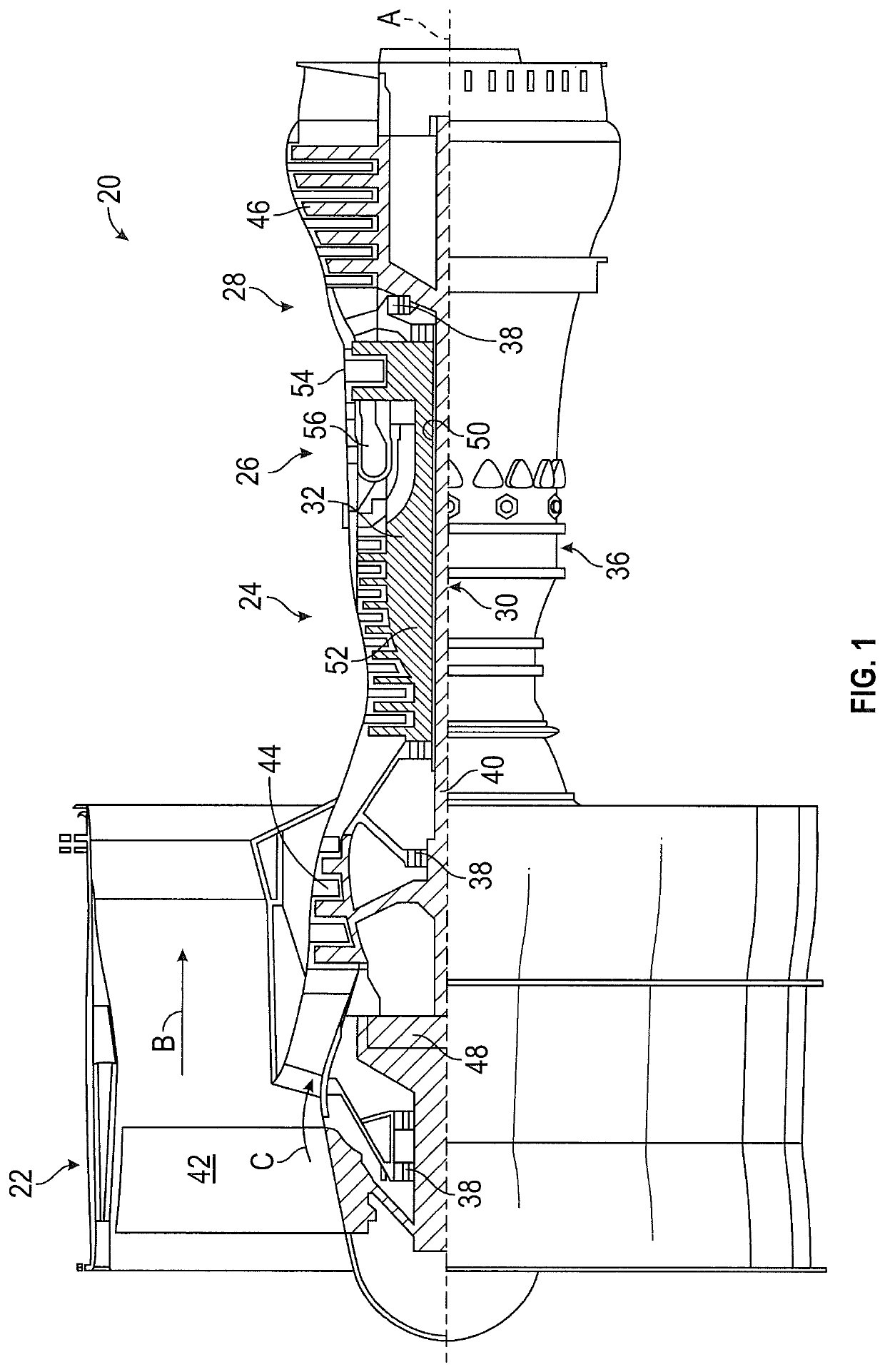
[0035]FIG. 1 schematically illustrates a gas turbine engine 20. The gas turbine engine 20 is disclosed herein as a two-spool turbofan that generally incorporates a fan section 22, a compressor section 24, a combustor section 26 and a turbine section 28. Alternative engines might include an augmentor section (not shown) among other systems or features. The fan section 22 drives air along a bypass flow path B in a bypass duct, while the compressor section 24 drives air along a core flow path C for compression and communication into the combustor section 26 then expansion through the turbine section 28. Although depicted as a two-spool turbofan gas turbine engine in the disclosed non-limiting embodiment, it should be understood that the concepts described herein are not limited to use with two-spool...


PUM


Abstract

A component for a gas turbine engine, includes a component outer surface exposed to flowpath gases of the gas turbine engine, a cooling channel located in the component, and at least one channel rib located in the cooling channel extending across the cooling channel from a channel inner surface to a channel outer surface. A cooling slot extends from the cooling channel to a slot outlet at the component outer surface. The slot outlet has a radial width greater than an axial length.

Description

BACKGROUND[0001]Exemplary embodiments pertain to the art of gas turbine engines, and more particularly to cooling of components of gas turbine engines.[0002]Advancements in performance of turbomachines, such as gas turbine engines, performance has often been linked to overall pressure ratio of the turbomachine and a turbine inlet temperature that can be sustained during operation of the turbomachine. Increases in efficiency through increases in pressure ratio and / or turbine inlet temperature typically results in an increase in operating temperatures of turbine flow path components, in which temperatures of the working fluid in the turbine flow path is often several hundred degrees Fahrenheit higher than the melting point of component materials.[0003]Components such as turbine vanes and blades and blade outer air seals, in the turbine section of the gas turbine engine are configured for use within particular temperature ranges. Often, the conditions in which the components are operat...

Claims


Application Information

Patent Timeline
Patent Type & Authority Patents(United States)
IPC IPC(8): F01D5/18F01D9/04F01D25/12F01D11/08
CPCF01D25/12F01D9/041F01D5/186F01D11/08F05D2220/323F05D2240/11F05D2240/12F05D2250/70F05D2240/30F05D2250/52F05D2260/202F05D2260/204F05D2260/22141Y02T50/60
Inventor LORICCO, NICHOLAS M.
Owner RTX CORP
Features
  • R&D
  • Intellectual Property
  • Life Sciences
  • Materials
  • Tech Scout
  • Unparalleled Data Quality
  • Higher Quality Content
  • 60% Fewer Hallucinations
Learn More