
Moving-coil closed-loop auto-focusing camera module with low magnetic interference

a closed-loop, camera module technology, applied in the direction of camera focusing arrangement, printers, magnetic bodies, etc., can solve the problems of inability to effectively reduce the magnetic interference of the conventional image-capturing module and the inability to image stable, and achieve the effect of effectively reducing the magnetic interference between the sensor magnet and the driving magn

Active Publication Date: 2020-07-28
POWERGATE OPTICAL INC
View PDF2 Cites 0 Cited by
  • Summary
  • Abstract
  • Description
  • Claims
  • Application Information

AI Technical Summary

Benefits of technology

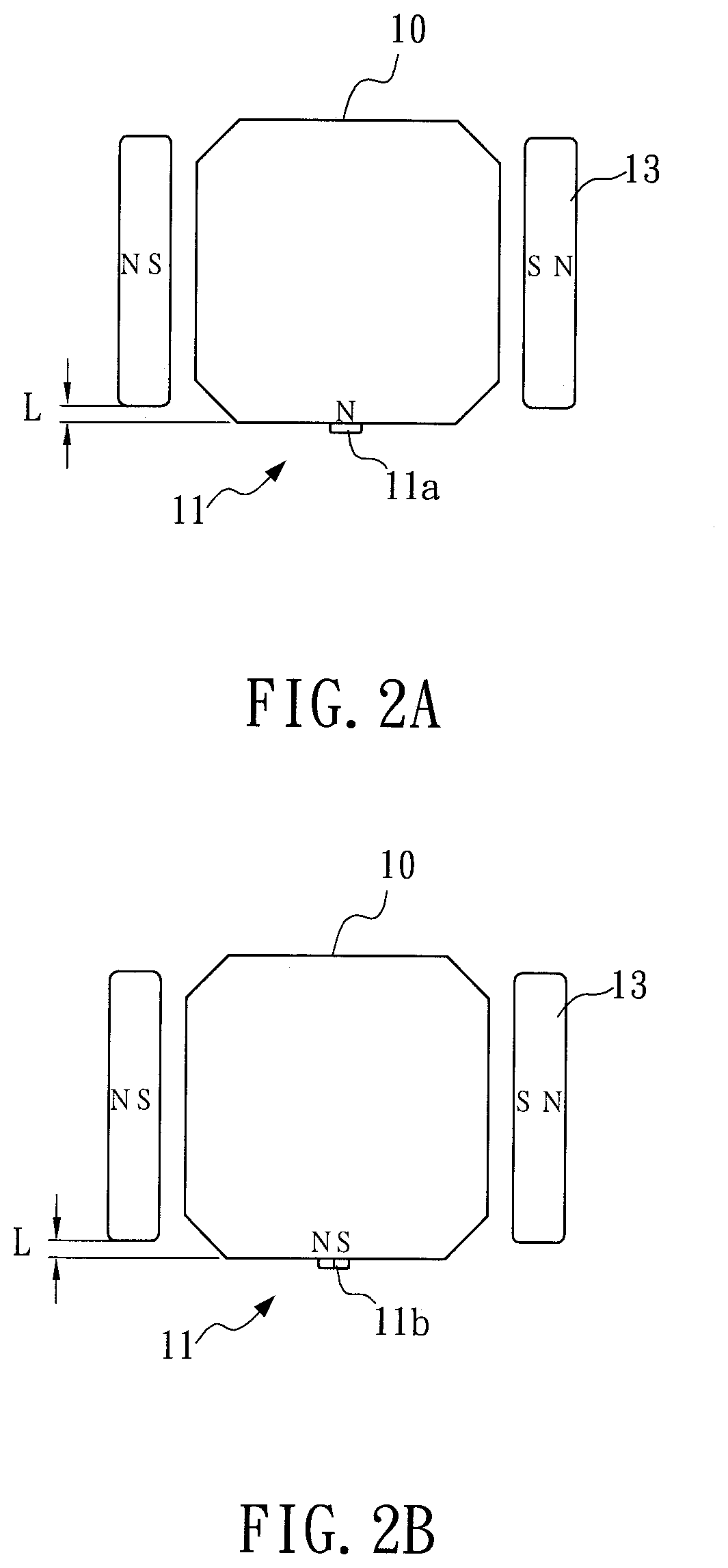
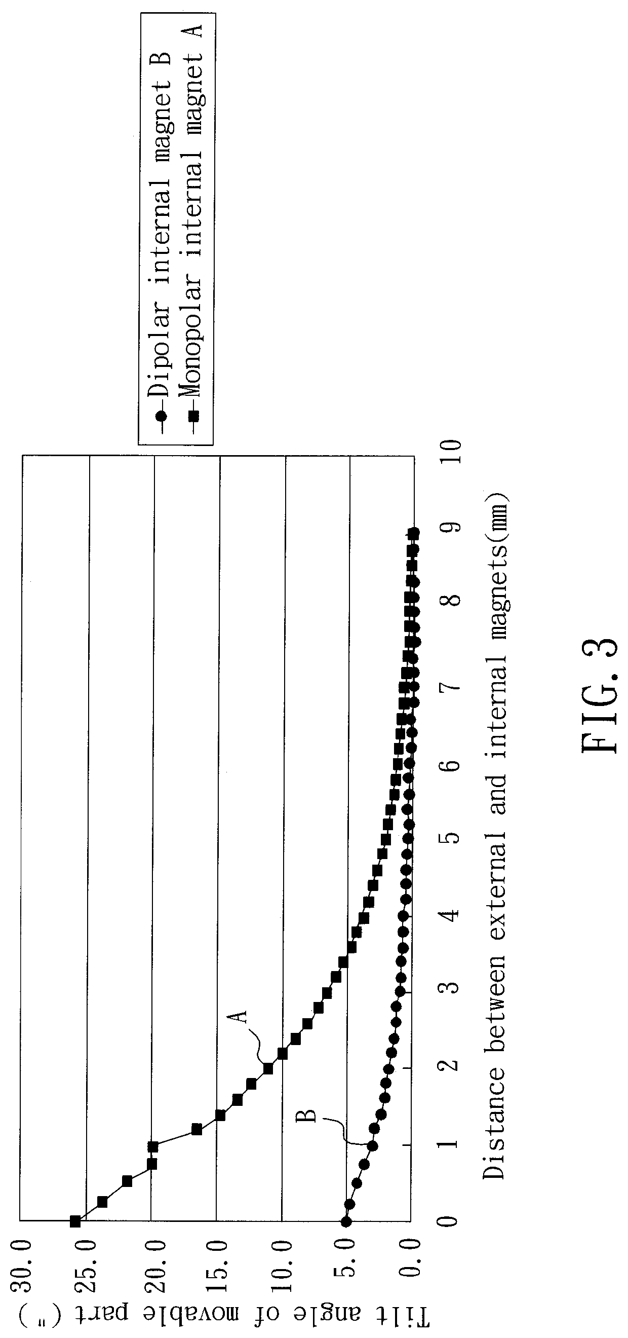
The present invention is a moving-coil closed-loop auto-focusing module with low magnetic interference. It uses a sensor magnet fixed at a lens and an external circuit to confirm the correct position of the lens. The magnetic interference between the sensor magnet and the driving magnets is effectively reduced through a preferred arrangement of magnetic fields. This results in improved image quality and reduced magnetic interference.

Problems solved by technology

In a conventional optical system consisted of a lens module and an image-compensating module, such as camera or video recorders, some unexpected foreign forcing or hand shakes may lead to bias of an optical path, and also cause unstable imaging at the image-compensating module.
It is noticed that the conventional image-capturing module features in poor capability against the magnetic interference, and, on the other hand, the dual-lens module should be kept distantly by predetermined spacing before an acceptable ability against the magnetic interference can be obtained.

Method used


Image

  • Moving-coil closed-loop auto-focusing camera module with low magnetic interference
  • Moving-coil closed-loop auto-focusing camera module with low magnetic interference
  • Moving-coil closed-loop auto-focusing camera module with low magnetic interference

Examples


Embodiment Construction

[0080]The invention disclosed herein is directed to a moving-coil closed-loop auto-focusing module with low magnetic interference. In the following description, numerous details are set forth in order to provide a thorough understanding of the present invention. It will be appreciated by one skilled in the art that variations of these specific details are possible while still achieving the results of the present invention. In other instance, well-known components are not described in detail in order not to unnecessarily obscure the present invention.

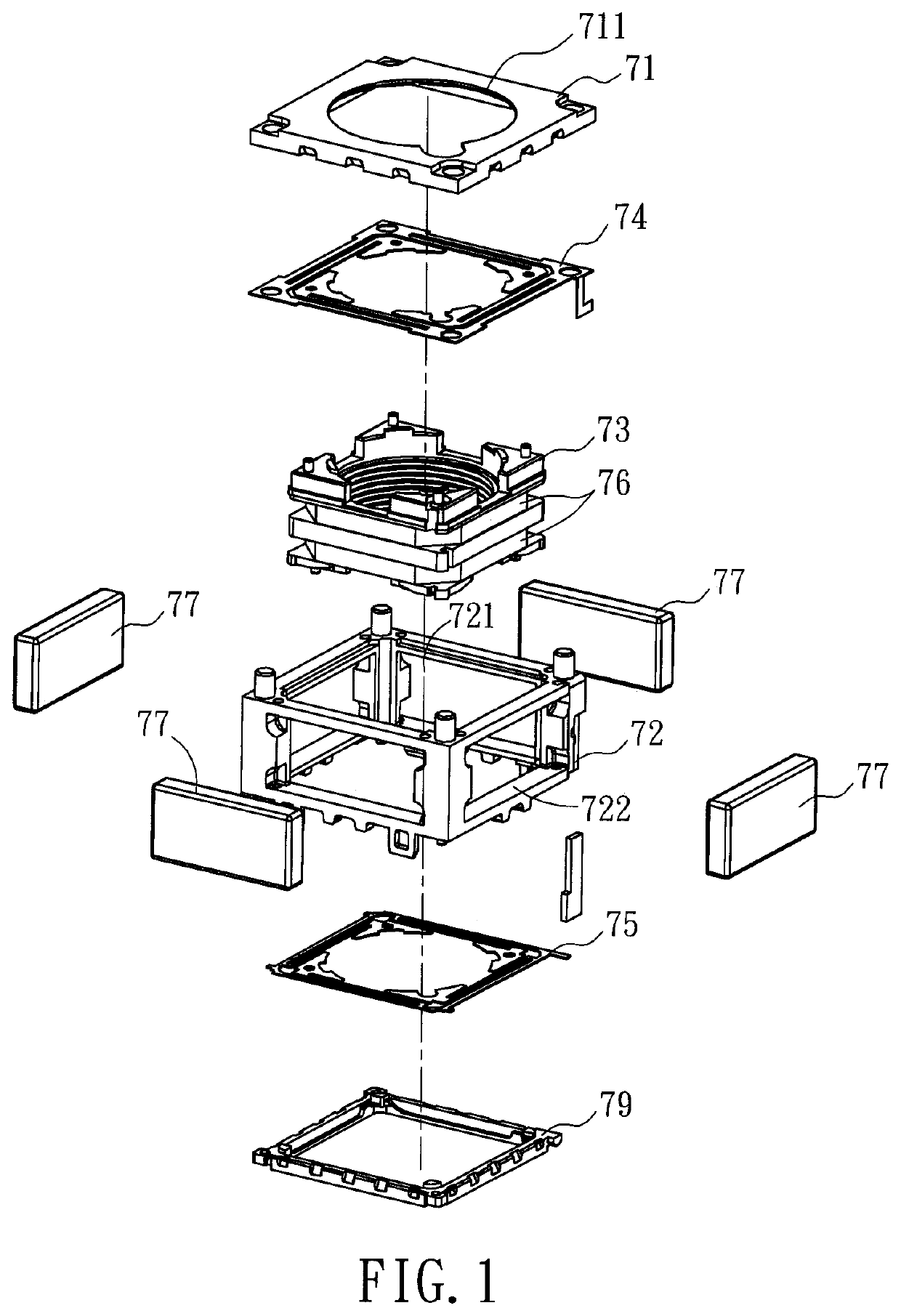
[0081]Referring now to FIG. 1, a schematic exploded view of a basic framework of the moving-coil auto-focusing camera module is shown. Generally in the art, the moving-coil auto-focusing camera module 7 is basically structured to include an upper cover 71, a base frame 72, a lens module 73, an upper spring plate 74, a lower spring plate 75, at least one coil 76, two pairs of opposite driving magnets 77, a connection plate 78 and a fixati...


PUM

PropertyMeasurementUnit
magnetismaaaaaaaaaa
polaritiesaaaaaaaaaa
polarityaaaaaaaaaa

Abstract

A moving-coil closed-loop auto-focusing module with low magnetic interference includes an upper cover, a base frame, a lens module, an elastic module, at least one coil, at least one pair of two opposing driving magnets, an external circuit and at least one sensor magnet. The coil surrounds the lens module. The two driving magnets are located individually at respective lateral sides of the base frame in correspondence with the coil. The external circuit located under the base frame includes an image-sensing element and at least one sensor. The sensor magnet is mounted peripherally to the lens module, and has magnetic lines parallel to the optical image-capturing axis, such that a magnetizing surface of the sensor magnet can face downward to align the sensor on the external circuit. Thereupon, the lens module can be controlled to displace along an optical image-capturing axis in a closed-loop manner.

Description

[0001]This application claims the benefit of Taiwan Patent Application Serial No. 106206702, filed on May 11, 2017, the subject matter of which is incorporated herein by reference.BACKGROUND OF INVENTION1. Field of the Invention[0002]The invention relates to a moving-coil closed-loop auto-focusing module with low magnetic interference, and more particularly to the moving-coil closed-loop auto-focusing module that achieves a goal of quick focusing by applying a sensor magnet and a sensor on an external circuit to detect displacements of a lens module in an optical image-capturing axis.2. Description of the Prior Art[0003]Progress in relative technology has minimized a size of digital camera. Currently, thanks to minimization of modern lens modules, various small-sized electronic devices (smart phones for example) can provide digital image-capturing functions. However, one of popular micro lens sets adopted by these electronic devices is the voice coil motor (VCM), which includes a co...

Claims


Application Information

Patent Timeline
Patent Type & Authority Patents(United States)
IPC IPC(8): G02B7/02G02B7/10G01D5/14G02B7/09H01F7/06G03B13/36G03B3/10H01F7/02G02B27/64
CPCG03B3/10H01F7/06H01F7/066H01F7/0289G03B13/36G01D5/145G02B7/10G02B7/09G03B2205/0069G02B27/646G02B7/08
Inventor HUANG, YING CHUNCHEN, YU CHIACHUANG, HSIEH JENHO, TE PAOWEN, SHIH CHAN
Owner POWERGATE OPTICAL INC
Learn More